Flow rates, Installation, Step 1 - determine the location of the flow switch – Xylem MM 615D Series FS1 High Sensitivity Liquid Flow Switch User Manual
Page 3: Psi flow switch capacity - fsi
P
10
20
30
40
50
60
70
80
90
8.35
11.50
13.60
15.75
17.75
19.75
21.25
23
24.25
Mode of Operation
Flow
No Flow
Settings
gpm (lpm)
gpm (lpm)
Factory or
Minimum
0.41 (1.55)
0.24
(.91)
25
Maximum
1.81 (6.85)
1.28
(4.84)
(95)
FLOW RATES
Settings will vary when used to sense flow of other
fluids.
3
NOTE: DO NOT USE LIQUID FLOW
SWITCHES
ON
SYSTEMS
WITH
FLOW VELOCITY GREATER THAN
10 FEET (3M) PER SECOND.
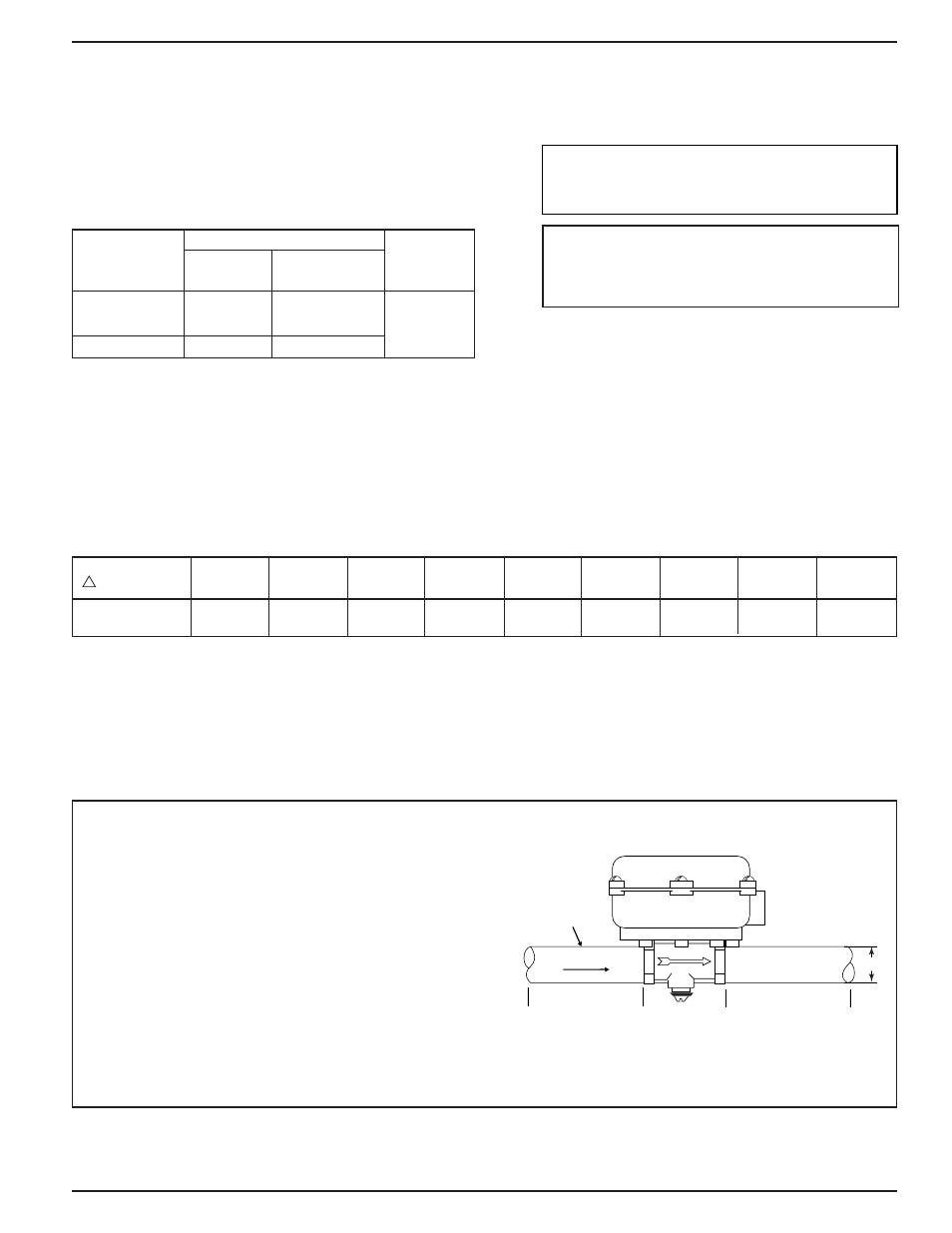
INSTALLATION –
STEP 1 - Determine the Location of the Flow Switch
D
5 x D
MINIMUM
1/2
" PIPE
5 x D
MINIMUM
FLUID FLOW
D= PIPE DIAMETER
• The flow switch should be located in a horizontal
section of pipe where there is a straight horizontal
run of at least 5 pipe diameters on each side of the
flow switch.
• The flow switch must be installed in the upright
position as shown with arrow mark on side of casting
in the same direction as fluid will flow.
• Some system conditions that require more than 5
pipe diameters are high viscosity fluid and high fluid
velocity.
NOTE: “L” models are set at the factory to prove flow at 1.7 gpm. The setpoint should not be adjusted in the
field without consulting factory.
Flow Rates
Values are ± 10%
Max. Flow Rate
gpm (lpm) w/o
Paddle Damage
PSI Flow Switch Capacity - FSI
DIFFERENTIAL
PRESSURE
GPM
CAPACITY
calculated using clean water in a horizontal pipe.
Flow rates required to activate the flow switch
are shown in chart below.These values were
NOTE: THIS PRODUCT IS NOT INTENDED
FOR USE IN POTABLE WATER
APPLICATIONS.