Installation, For 193-d models – Xylem MM 404J Series 93/193 and Series 94/194 Low Water Cut-Off/Pump Controllers For Steam Boilers and Level Control Applications User Manual
Page 4
4
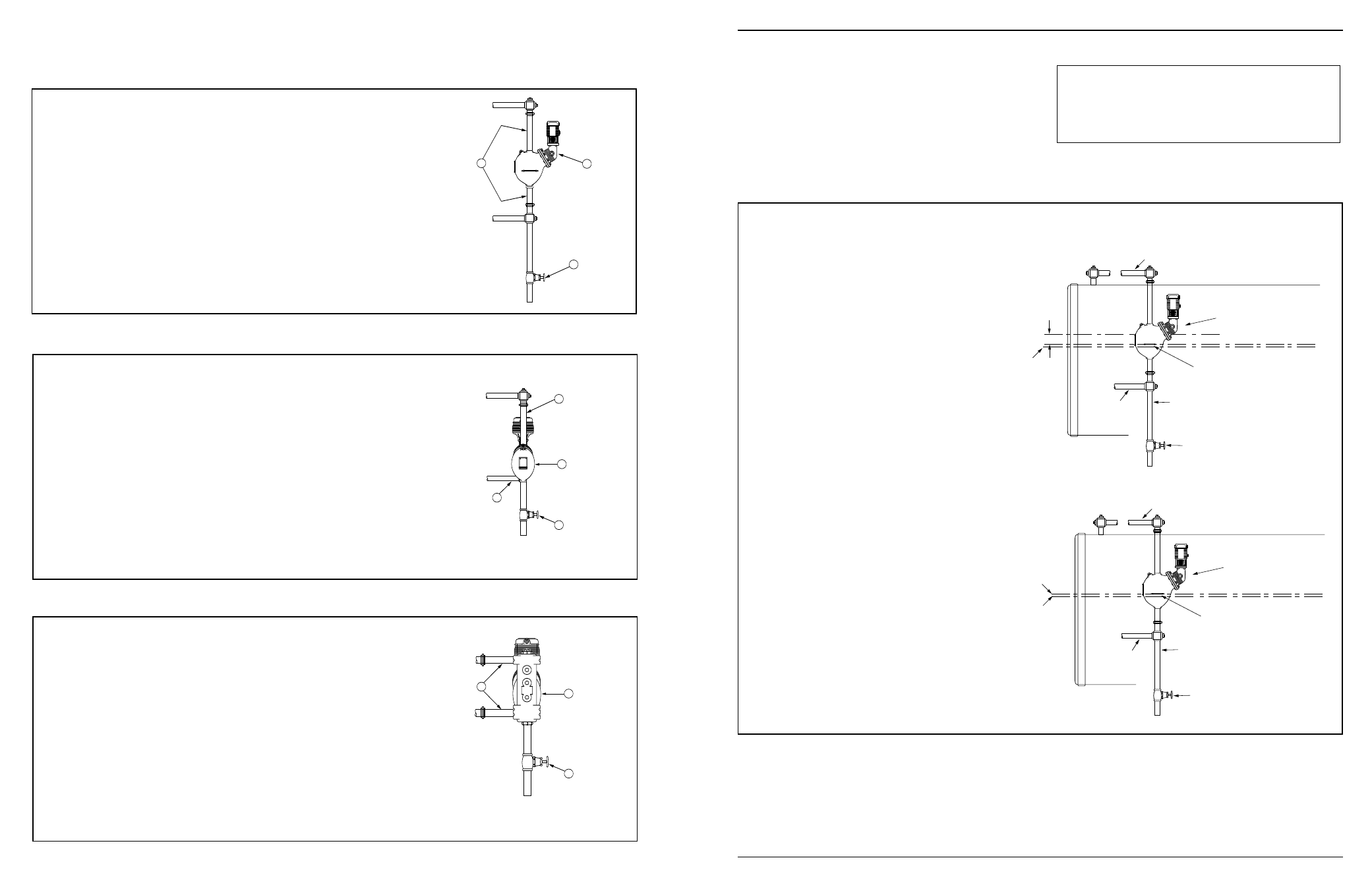
A
B
C
a. Mount and pipe the control (A) on vertical equalizing
pipes (
B) at the required elevation as determined in
Step 1.
Install a full-ported blow-down valve (
C) directly
below the lower cross.
NOTE:
1” (25mm) NPT tappings are provided on Series
93/193 controls.
1 1/4” (32mm) NPT tappings are provided for Series
94/194 controls and 193-B Model.
STEP 2 - Installing the Low Water Cut-Off/Pump Controller
For Series 93/193 or 94/194 (except 94-A, 193-D and 193-G Models)
A
E
C
D
a. Mount and pipe the control (A) with a vertical upper
(
D) and horizontal lower (E) equalizing piping at the
required elevation as determined in Step 1.
Install a full-ported blow-down valve (
C) on the lower
body connection.
NOTE:
1 1/4” (32mm) NPT tappings are provided for 94-A
Model control.
1” (25mm) NPT tappings are provided for 193-G
Model control.
For 94-A and 193-G Models
A
C
G
a. Mount and pipe the control (A) with a horizontal
upper and lower (
G) equalizing piping at the
required elevation as determined in Step 1.
Install a full-ported blow-down valve (
C) on the lower
body connection.
NOTE:
1” (25mm) NPT tappings are provided for 193-D
Model control.
For 193-D Models
3
If the control will be the primary low
water fuel cut-off, size the steam (top) and
water (bottom) equalizing pipe lengths so
that the horizontal cast line on the body is
1 1/2” (38mm) below the boiler’s normal
water level,
but not lower than the lowest
safe permissible water level, as deter-
mined by the boiler manufacturer.
OR
If the control will be the secondary low
water fuel cut-off, size the steam (top) and
water (bottom) equalizing pipe lengths so
that the horizontal cast line on the body is
at or above the lowest safe permissible
water level, as determined by the boiler
manufacturer.
STEP 1 - Determine the Position of the Low Water Cut-Off/Pump Controller
INSTALLATION –
TOOLS NEEDED:
Two (2) pipe wrenches, one (1) flathead screw
driver, and pipe thread dope.
IMPORTANT: Follow the boiler manufacturer's
instructions along with all applicable codes and
ordinances for piping, blow-down valve, water
gauge glass, tri-cock and electrical requirements.
1
1
/
2
"
STEAM EQUALIZING PIPE
VERTICAL EQUALIZING PIPE
BLOW DOWN VALVE
NORMAL BOILER WATER LINE
AS A PRIMARY
LOW WATER CUT-OFF/PUMP
CONTROLLER
BURNER “CUT-OFF LEVEL”
AT CAST LINE
LOWEST
PERMISSIBLE
WATER LEVEL
WATER
EQUALIZING
PIPE
STEAM EQUALIZING PIPE
VERTICAL EQUALIZING PIPE
BLOW DOWN VALVE
AS A SECONDARY
LOW WATER CUT-OFF/PUMP
CONTROLLER
BURNER “CUT-OFF LEVEL”
AT CAST LINE
LOWEST
PERMISSIBLE
WATER LEVEL
BURNER OFF
WATER
EQUALIZING
PIPE