Operation capacities, Typical installations – Xylem MM 317C Models 21 & 221 Mechanical Water Feeders User Manual
Page 2
2
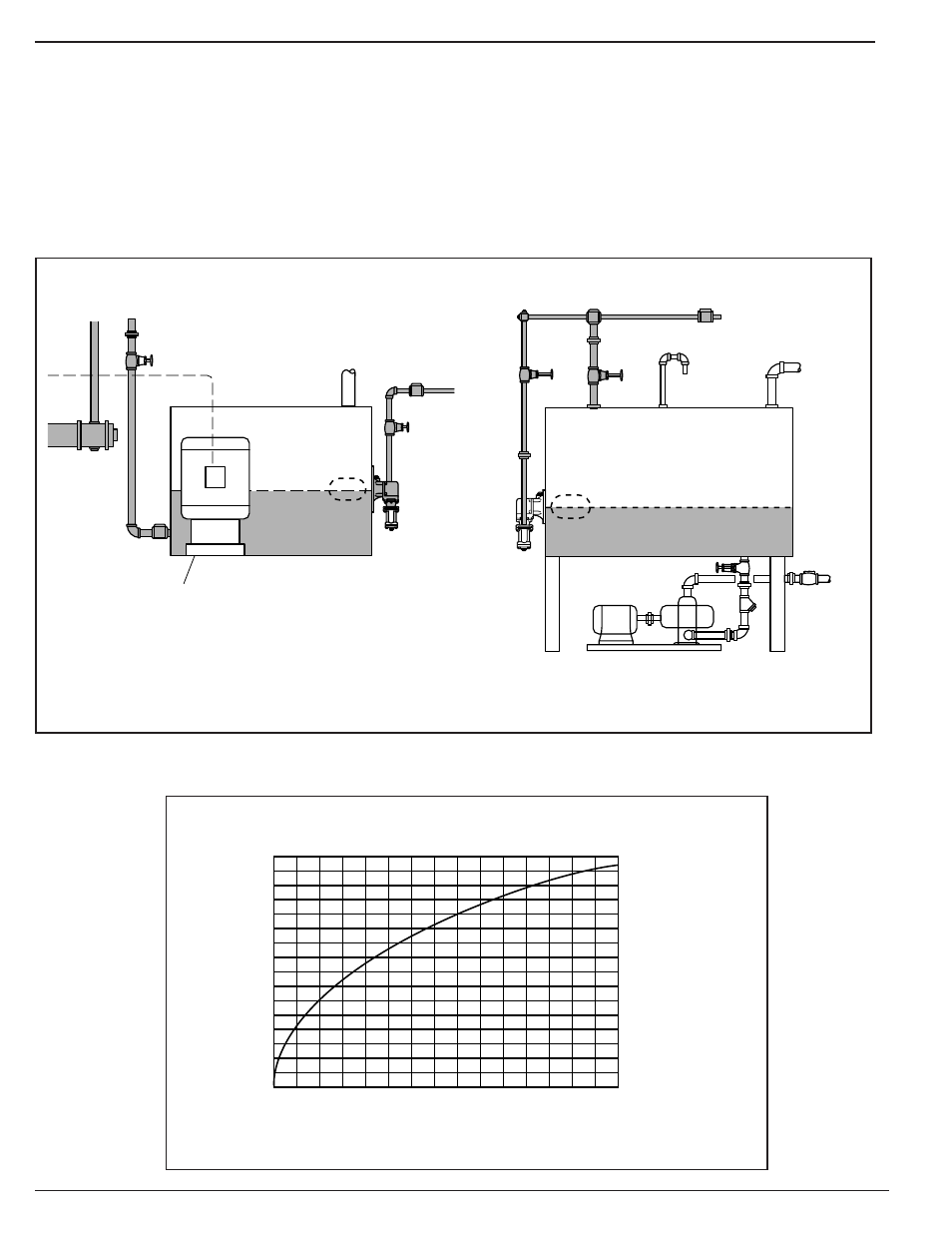
OPERATION
Capacities
WATER SUPPLY PRESSURE IN LBS. PER SQ. IN.
CAPACITY CURVE
lbs./hr.
psi
(kg/hr.)
130
120
110
100
90
80
70
60
50
40
30
10
16,000
15,000
14,000
13,000
12,000
11,000
10,000
9,000
8,000
7,000
6,000
5,000
4,000
3,000
2,000
1,000
0
(7258)
(6804)
(6350)
(5897)
(5443)
(4990)
(4536)
(4082)
(3629)
(3175)
(2722)
(2268)
(1814)
(1361)
(907)
(454)
(0)
(0.7)(1.4)(2.1)(2.8)(3.5)(4.2)(4.9)(5.6)(6.3)(7.0)(7.7)(8.4)(9.1)(9.8)(10.5)
20
0
(0)
140 150
32
30
28
26
24
22
20
18
16
14
12
10
8
6
4
2
0
(121.12)
(113.55)
(105.98)
(98.41)
(90.84)
(83.27)
(75.70)
(68.13)
(60.56)
(52.99)
(45.42)
(37.85)
(30.28)
(22.71)
(15.14)
(7.57)
(0)
(kg/cm
2
)
gpm
(lpm)
464
435
406
377
348
319
290
261
232
203
174
145
116
87
58
29
0
(4549)
(4264)
(3980)
(3696)
(3411)
(3127)
(2843)
(2559)
(2274)
(1990)
(1706)
(1421)
(1137)
(853)
(569)
(284)
(0)
Boiler Hp
(kilowatts)
The Series 21 make-up water feeder provides
dependable, float-operated automatic water filling
service to tanks used as condensate receivers in
boiler systems. The valve components are of brass,
an elastomer sealing disc and stainless steel materi-
als, and a 4-3/4” diameter copper float providing
closure against supply pressure up to 150 PSI. An
integral strainer and housing with removable drainage
plug precede the valve for regular servicing. The con-
trol is a direct-feeding unit (feeds through the flange
connection) available in two flange sizes.
TYPICAL INSTALLATIONS
MODEL 221
Boiler
Feed
Tank
Feed Pump
City Water Supply
Check Valve
Bypass
Condensate Receiver Tank
Pump
Discharge
Feed Pump
MODEL 21