Step 3 - installing the control box, Step 4 - electrical wiring, Important – Xylem MM 273E Model 750-HW-MT-120 Probe Type High Water Manual Reset Control Unit User Manual
Page 5: Warning
5
C
D
E
(x2)
Model 750-HW-MT-120
Probe Type High Water
Control Unit
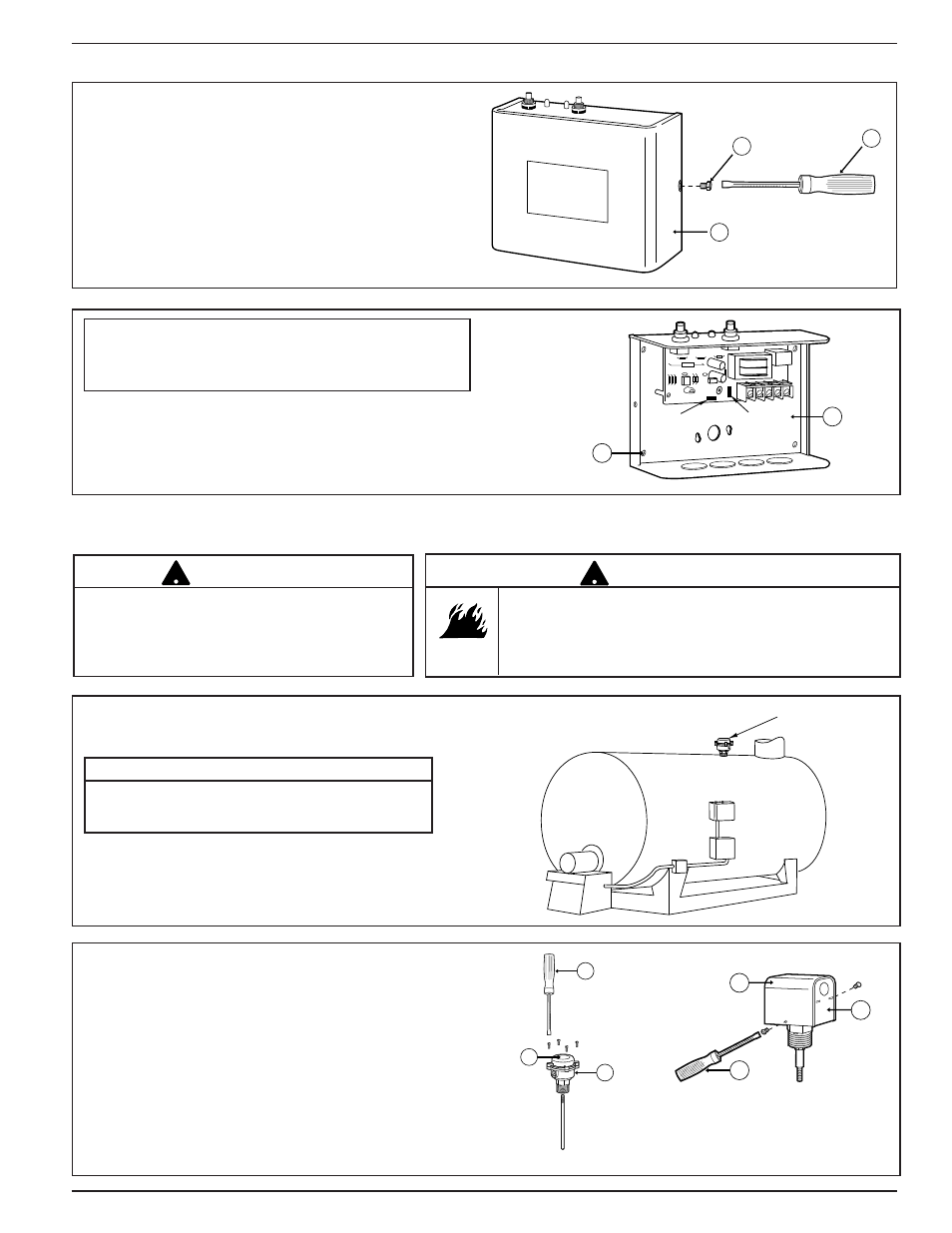
a. Using the flatblade screwdriver or nut driver (C),
loosen the two (2) screws (D) and remove
cover (E).
G
F
(x4)
b. Using the four (4) 3/16" (4.8mm) mounting
holes (F), attach the control (G) to the boiler
jacket, entry plate, or other suitable location.
NOTE: Mounting hardware is not included.
STEP 3 - Installing the Control Box
IMPORTANT: To protect control from damage
caused by liquid or debris, mount as shown with
buttons on top.
STEP 4 - Electrical Wiring
Boiler manufacturer schematics should always be
followed. In the event that the boiler manufacturer’s
schematic does not exist, or is not available from
the boiler manufacturer, refer to the schematics
provided in this document.
!
IMPORTANT
To prevent an electrical fire or equipment damage,
electrical wiring must have a rating of 167˚F (75˚C) if the
liquid's temperature exceeds 180˚F (82˚C).
Failure to follow this warning could cause property
damage, personal injury or death.
!
WARNING
RS1-BR-1
SENSOR
• Mount Control Box in a suitable location near
the boiler’s main electrical panel.
Boiler sight glass must be visible from location of
Control Box and must be within 25 feet of Control
Body.
NOTE
a. Remove the sensor housing cover (Q).
1. For Model RS-1-BR-1, using a flathead
screwdriver (R), remove the four (4) screws
and separate the housing cover (Q) from the
sensor (B).
2. For Model RS-1-LP, using a flathead screw-
driver or nut driver (R), loosen the two (2)
screws and separate the housing cover (Q)
from the sensor (B).
B
R
Q
R
Q
B
Model RS-1-BR-1
Model RS-1-LP
OR
GND
PROBE