Step 4 - control wiring (continued), Installation complete, Caution – Xylem MM 284D Series PSE-800 Probe Type Low Water Cut-Off for Steam Boilers User Manual
Page 6
6
STEP 4 - Control Wiring (continued)
N
P
M
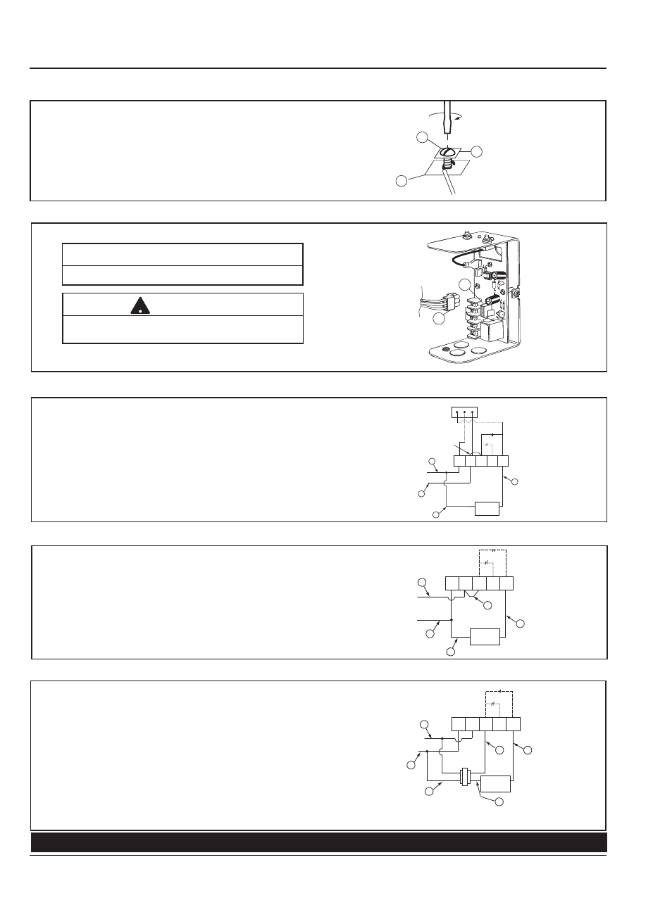
d. For all wire connections to the terminal block (M).
1.Strip about 1/3" (8.5 mm) of insulation from the wire.
2.Loosen the terminal screw (N) but DO NOT
REMOVE. Move the wire clamping plate (P) back until the
plate touches the back side of the screw head.
3.Insert the stripped end of the wire under the wire clamping
plate (P) and securely tighten the terminal screw (N).
INSTALLATION COMPLETE
E
H
N
H
C
W
B
BURNER
CIRCUIT
C
B
D
A
N
120 VOLT
CIRCUIT
• Connect Hot wire (A) of 120 volt circuit to terminal (H).
• Connect Neutral wire (B) of 120 volt circuit to terminal (N).
• Connect wire (C) from beginning of Burner circuit (thermostat,
gas valve, limits, etc.) to terminal (B).
• Connect wire (D) from end of Burner circuit to terminal (N).
• Connect jumper wire (E) to terminals (H) and (C).
PSE-801 with 120 Volt Burner Circuit
E
H
N
H
C
W
B
BURNER
CIRCUIT
E
C
B
A
N
120 VOLT
CIRCUIT
L
1
L
2
T
1
T
2
24 VOLT
TRANSFORMER
(BY OTHERS)
D
• Connect hot wire (A) of 120 volt circuit to terminal (H) and
transformer terminal (L1).
• Connect neutral wire ‘B’ of 120 volt circuit to terminal (N) and
transformer terminal (L2).
• Connect wire (C) from beginning of Burner circuit
(thermostat, gas valve, limits, etc.) to terminal (B).
• Connect wire (D) from end of Burner circuit to transformer
terminal (T2).
• Connect wire (E) from transformer terminal (T1) to
terminal (C).
PSE-801 with 24 Volt Burner Circuit
A
B
Wiring harness is provided by boiler manufacturer.
NOTE
Do not use force to insert plug. This may damage
receptacle solder connections.
!
CAUTION
Connect plug (A) of wiring harness to receptacle (B).
Check to make sure factory supplied jumper is installed
between terminals (H) and (C).
PSE-802 using Harness Connection
PSE-802 using Terminal Connections
D
N
H
C
W
B
BURNER
CIRCUIT
C
B
A
24 VOLT
POWER
CIRCUIT
JUMPER
BAR
N H
B
• Connect neutral wire (A) of 24 volt circuit to terminal (N).
• Connect hot wire (B) of 24 volt circuit to terminal (H).
• Connect wire (C) from beginning of Burner circuit
(thermostat, gas valve, limits, etc.) to terminal (B).
• Connect wire (D) from end of Burner circuit to terminal (N).
• Make sure factory provided jumper bar is connected to
terminal (H) and (C).