Wiring diagrams, Step 3 - electrical wiring, Warning – Xylem MM 243D Replacement Head Mechanism 42S HD User Manual
Page 5
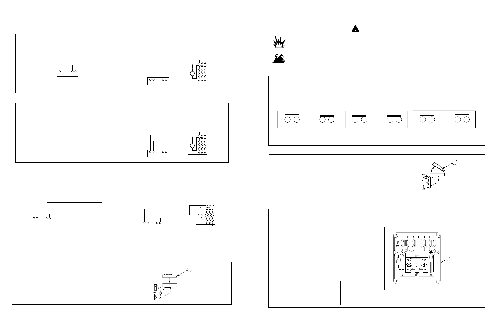
WIRING DIAGRAMS
Low Water Cut-Off Only
1. Main Line Switch - For burner circuits within the
switch’s electrical rating.
Pump Control Only
1. Install a starter or relay in pump control circuit,
as shown, to prevent damage to snap switch
and help insure proper switch/control operation.
Failure to do so may shorten the life of the switch
when actual amperage exceeds switch rating.
2. Connect wires from holding coil of pump starter
or relay to terminals 1 and 2 as shown.
NOTE: To help insure most effective operation,
balance boiler feed pump(s) to deliver required water
feed rate to match boiler steaming requirements.
LINE
LOAD
1 2
5 6
12
56
LOAD
LINE
12
56
LOAD
LINE
OR
2. Pilot Switch - To holding coil of a starter when
the burner circuit exceeds the switch’s electrical
rating.
6
1. Main Line Switch - For burner circuits within
the switch’s electrical rating.
2. Pilot Switch - To holding coil of a starter when
the burner circuit exceeds the switch’s electrical
rating.
12
56
SEE PUMP
CONTROL
CIRCUIT
TO BURNER CONTROL CIRCUIT
HOT
12
56
LOAD
LINE
SEE PUMP
CONTROL
CIRCUIT
OR
Combination Pump Control, Low Water Cut-Off and Alarm
B
c. Re-attach the junction box cover (B).
5
B
STEP 3 - Electrical Wiring
a. Using a flathead screwdriver, remove the
junction box cover (B).
b. Following the appropriate wiring
diagram, (refer to page 6)
based on your application
requirements, and using BX
armored cable or Thinwall elec-
trical metal tubing connector fit-
tings, make electrical connec-
tions to the junction box (K).
Note: Follow local codes and stan-
dards when selecting the types of
electrical fittings and conduit to
connect to control.
• To prevent electrical shock, turn off the electrical power before making electrical connections.
• This low water cut-off must be installed in series with all other limit and operating controls installed on the
boiler. After installation, check for proper operation of all of the limit and operating controls, before leaving
the site.
Failure to follow this warning could cause electrical shock, an explosion and/or a fire, which could result in
property damage, personal injury or death.
!
WARNING
K
Switch Operation
Snap Switches
(Series 42S)
Boiler feed pump off,
burner on.
Boiler feed pump on,
burner on.
Boiler feed pump on,
burner off.
IMPORTANT: There must be a
minimum space of 1/2” (13mm)
between connector fittings and
electrical live metal parts.
1
2
5
6
Boiler feed pump off-
burner on.
1
2
5
6
Boiler feed pump on-
burner on.
1
2
5
6
Boiler feed pump on-
burner off.
1
2
5
6
1
2
5
6
1
2
5
6