Operation, Diagram 1 diagram 2, Diagram 3 diagram 4 – Xylem MM 226C Series 69 Low Water Cut-Offs For Steam Boilers User Manual
Page 2: Dimensions, in. (mm), Maximum steam pressure: 20 psi (1.4 kg/cm, Electrical ratings, Dc f b e
2
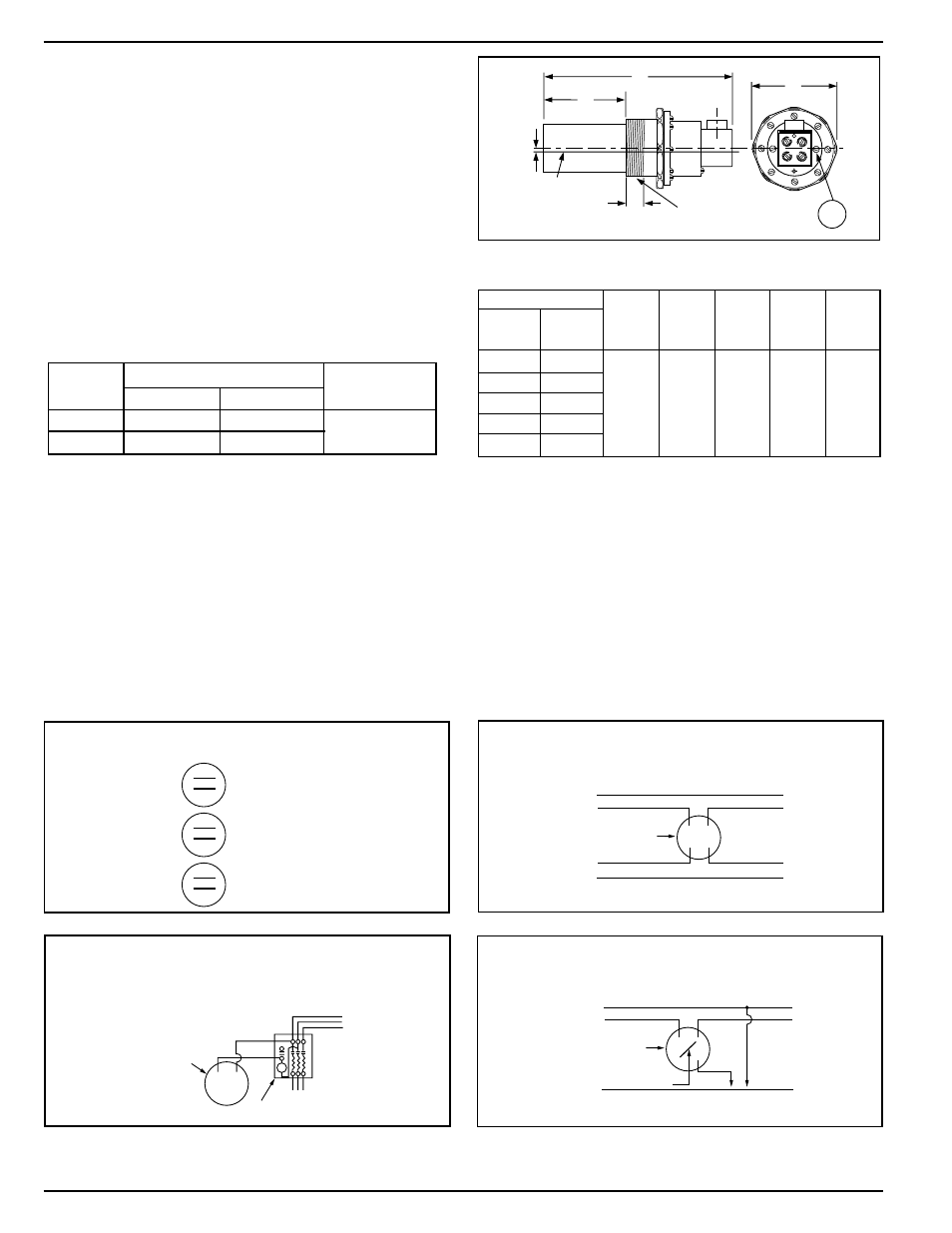
The 69 Series Built-in Low Water Cut-Off is furnished
with a threaded barrel casting which fits right into a
2 1/2" tapping provided by some boiler manufacturers
in the side of the boiler. Selection of the particular
model depends upon the insertion length into the
boiler (see chart). Order the built-in which provides
maximum insertion within the boiler.
0
2
0
4
1
0
3
0
0
2
0
4
1
0
3
0
0
2
0
4
1
0
3
0
SCHEMATIC OF TWIN SWITCH
INTERNAL OPERATION
NORMAL WATER LEVEL
FEEDER OR ALARM
OPERATING LEVEL
LOW WATER CUT-OFF
OPERATING LEVEL
NEUTRAL WIRE
NEUTRAL WIRE
HOT WIRE
HOT WIRE
TO BURNER
TO ALARM
SAFETY
SWITCH
0
2
0
4
1
0
3
0
USED AS MAIN LINE SWITCH
Diagram 1
Diagram 2
TO LINE
TO BURNER
STARTER
SAFETY
SWITCH
L1
L2
L3
0
2
0
4
1
0
3
0
USED AS PILOT SWITCH IN SERIES WITH
HOLDING COIL OF AUTOMATIC STARTER
NEUTRAL WIRE
TO
TWO WIRES OF 101A
OR TO ALARM CIRCUIT
HOT WIRE
TO BURNER
JUMPER
SAFETY
SWITCH
0
2
0
4
1
0
3
0
USED WITH MODEL 101 ELECTRIC
WATER VALVE OR IN ALARM CIRCUIT
Diagram 3
Diagram 4
IMPORTANT: Low water cut-off circuit of the 69 series must be electrically wired in series with all other boiler
limit operating controls.
Based on desired usage, connect wires from low water cut-off to appropriate control/alarm.
OPERATION
Maximum Steam Pressure: 20 psi (1.4 kg/cm
2
)
Electrical Ratings
Motor Switch Rating (Amperes)
Voltage
Full Load
Locked Rotor
Pilot Duty
125 VA at
120 or 240 VAC
A
B
C
D
E
F
Insertion
Model
Length
NPT
69
4
1
⁄
8
(105)
169
3
1
⁄
8
(79)
269
2
1
⁄
4
(57) 1 (25) 4
1
⁄
8
(105)
1
⁄
8
(3)
2
1
⁄
2
9
1
⁄
2
(241)
369
1
3
⁄
4
(45)
469, 569 1
3
⁄
16
(30)
Dimensions, in. (mm)
1
2
3
4
D
C
F
B
E
CUT-OFF
LEVEL
A
AA
NOTE: MV models are rated at 24 VA @ 24 VAC to 120 VAC
120 VAC
7.4
44.4
240 VAC
3.7
22.2