Test-n-check, Valves – Xylem MM 214E Series 61 Low Water Cut-Off User Manual
Page 4
4
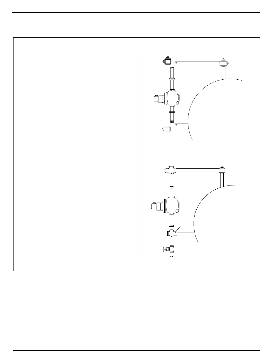
1. Assemble the TC-U (the upper Test-N-Check
valve, with the vacuum breaker) into the upper
equalizing line in place of the cross described
in the low water cut-off installation instructions.
NOTE: The vacuum breaker must be on the top
and the long leg must face the boiler. NOTE:
Make sure low water cut-off position is located
in accordance with the boiler manufacturer
recommended cut-off level.
2. Assemble the TC-L (the lower Test-N-Check
valve, without the vacuum breaker) into the
lower equalizing line in place of the cross
described in the low water cut-off installation
instructions. NOTE: The brass cap must be
located above the center of the lower equalizing
line, and the long leg must face the boiler.
3. Assemble the blow-off valve into the bottom
port of the TC-L.
4. Assemble 1” NPT pipe plugs into the remaining
open port in both the TC-U and TC-L.
5. Complete the installation as described in the
low water cut-off installation instructions.
6. After all piping assembly has been completed,
refill the system with water, turn on all electrical
supply and bring system to operating condi-
tions. After system reaches operating pressure,
inspect to make sure no leaks exist at the
threaded connections. Test valves by opening
blow-off valve while burner is on, to make sure
valves operate correctly and low water cut-off
shuts burner off.
TEST-N-CHECK
®
VALVES
Installation of the TC-4 Test-N-Check Valve with a New Low Water Cut-off
IMPORTANT:
•
Installation should be performed by qualified personnel only, in accordance with all applicable codes.
•
If vacuum breaker stem is accidentally depressed, hot water could be discharged causing burns.
•
Blow-off valve drain piping should be piped to a suitable drain to handle hot water and steam discharge,
and should be the same size as the equalizing pipe.
TC-U in Place
Blow-off Valve
TC-L
in Place
LWCO
Brass
Cap
REMOVE CROSS
LWCO
MM-214(C) 9/5/06 9:40 AM Page 5