Test-n-check, Valves – Xylem MM 206F Series 63 Low Water Cut-Off User Manual
Page 4
4
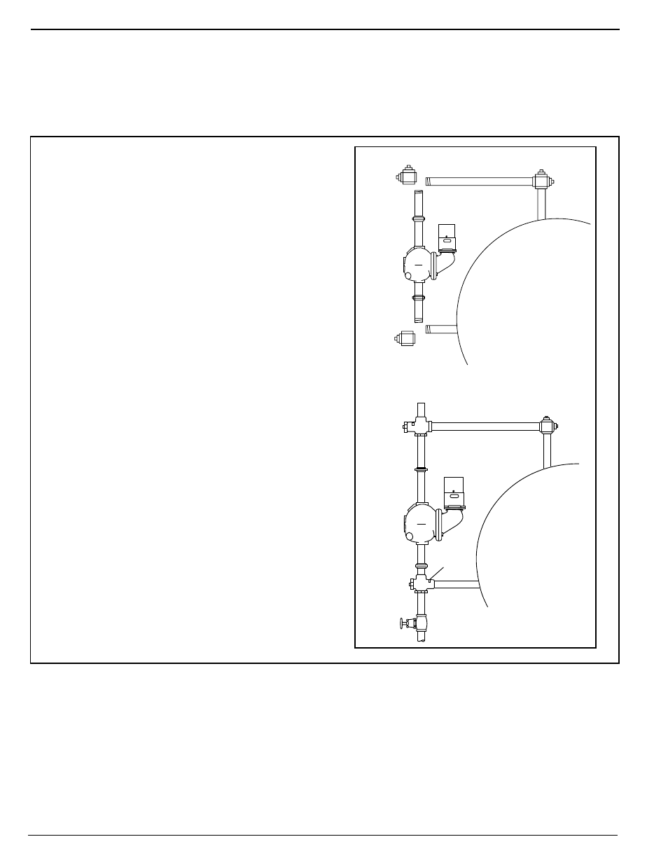
1. Assemble the TC-U (the upper Test-N-Check
valves, with the vacuum breaker) into the upper
equalizing line in place of the cross described
in the low water cut-off installation instructions.
NOTE: The vacuum breaker must be on the top
and the long leg must face the boiler. NOTE:
Make sure low water cut-off position is located
in accordance with the boiler manufacturer’s
recommended cut-off level.
2. Assemble the TC-L (the lower Test-N-Check
valve, without the vacuum breaker) into the
lower equalizing line in place of the cross
described in the low water cut-off installation
instructions. NOTE: The brass cap must be
located above the center of the lower equalizing
line, and the long leg must face the boiler.
3. Assemble the blow-off valve into the bottom
port of the TC-L.
4. Assemble 1” NPT pipe plugs into the remaining
open port in both the TC-U and TC-L.
5. Complete the installation as described in the
low water cut-off installation instructions.
6. After all piping assembly has been completed,
refill the system with water, turn on all electrical
supply and bring system to operating
conditions. After system reaches operating
pressure, inspect to make sure no leaks exist at
the threaded connections. Test valves by
opening blow-off valve while burner is on, to
make sure valves operate correctly and low
water cut-off shuts burner off.
Simplify Testing of Low Water Cut-offs on Hot Water Boilers
TEST-N-CHECK
®
VALVES
Installation of the TC-4 Test-N-Check valves with a New Low Water Cut-off
IMPORTANT:
•
Installation should be performed by qualified personnel only, in accordance with all applicable codes.
•
If vacuum breaker stem is accidentally depressed, hot water could be discharged causing burns.
•
Blow-off valve drain piping should be piped to a suitable drain to handle hot water and steam discharge,
and should be the same size as the equalizing pipe.
TC-U in Place
Blow-off Valve
TC-L
in Place
LWCO
Brass
Cap
REMOVE CROSS
LWCO