Bell & Gossett V59074B Low Flow Circuit Sentry Model ACL Flow Limiting Valves User Manual
Page 3
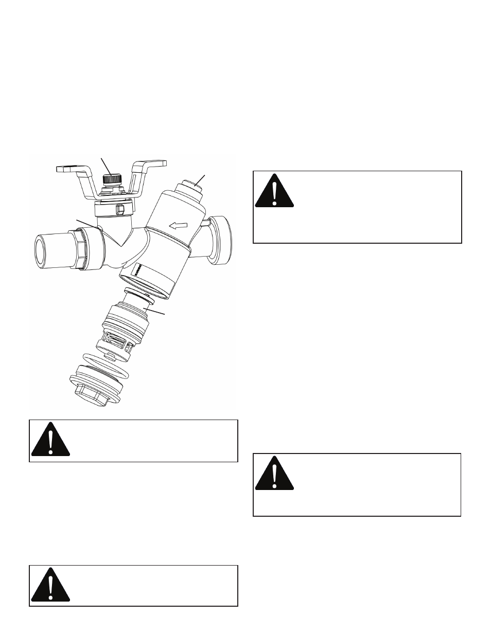
Prior to coil commissioning and operating the Flow
Limiting Valve, adjust cartridge to the desired flow rate
between 0.25 GPM to 3.8 GPM.
1.
Loosen screw (a) position.
2.
Rotate plastic dial (b) to the desired flow rate.
Increments marked on variable orifice are in GPM.
3.
Re-tighten screw (a) with dial set at the desired
flow rate.
4.
Install the cartridge as shown below.
OPERATION INSTRUCTIONS
HOW TO USE BELL & GOSSETT LOW FLOW CIRCUIT
SENTRY MODEL ACL FLOW LIMITING VALVES FOR
PRE-SET FLOW BALANCING
Operation of the Flow Limiting Valve is fully automatic.
It automatically maintains the selected flow over the
designed differential pressure range.
CAUTION: Make sure Valve Cap is properly
assembled. Failure to follow these
instructions can result in personal injury and/
or property damage.
Before system start up, remove the flow limiting cartridge
from the valve, if previously installed. Flush the hydronic
system as part of commissioning and then reassemble
cartridge into the valve. Make sure the valve cap is
tightened properly. Start the system and inspect the Low
Flow Circuit Sentry ACL valve for leakage.
HOW TO USE PRESSURE TAPS (P/T PORTS) TO MEASURE
SYSTEM OPERATING CONDITIONS
Using Bell & Gossett Model RP-250B, readout probes,
attach Bell & Gossett differential pressure readout kit to
the readout valves (P/T ports) on the Low Flow Circuit
Sentry ACL valve.
Read the differential pressure from the coil inlet
isolation valve (typically strainer) to coil isolation valve
(typically a flow limiting balancing valve). The
differential value minus the pressure drops across the coil
and installed control valves should be less than 60 psi for
proper flow control.
If more accurate readings are desired, a pressure readout
valve (B&G P/N V58050) may be installed (B) in the barrel
above the cartridge chamber of the flow limiting valve.
Pressure readings should then be taken from the P/T valve
located in the isolation valve (A) and the P/T valve located
in the barrel of the cartridge (B). The differential valve
should be less than 60 psi for proper control.
CAUTION: Hot un-insulated surfaces can
cause burns to the skin. Do not touch hot
surfaces. Failure to follow these instructions
could result in personal injury.
WARNING: Hot water leakage can occur
from readout valves (P/T ports) during probe
insertion and during hookup of readout kit.
Follow the instruction manuals supplied
with readout probes and readout kits for safe use.
Failure to follow these instructions could result in
serious personal injury or death and property damage.
SERVICE INSTRUCTIONS
Periodically inspect the Low Flow Circuit Sentry Model
ACL Flow Limiting Valve for signs of leakage or corrosion.
Replace valve cap o-ring (V57754), if necessary
WARNING: Corrosion or leakage are
indications that the Low Flow Circuit Sentry
Model ACL Flow Limiting Valve must be
replaced. Failure to follow these
instructions could result in serious personal injury or
death and property damage.
Due to the different types of material used, the Low Flow
Circuit Sentry Model ACL Flow Limiting Valve must be
disassembled prior to disposal. Special handling of
certain valve components may be required by law or may
be sensible from an ecological point of view.
Isolation Valve
Installed P/T Port (A)
Flow Cartridge
Optional P/T
Port (B)