Installation instructions – Xylem Parshall flumes User Manual
Page 2
2
Installation instructions
MJK Automation A/S
Byageren 7
DK-2850 Nærum
Denmark
Tel.: (+45) 45 56 06 56
Fax: (+45) 45 56 06 46
[email protected]
www.mjk.dk
Mounting of the flume
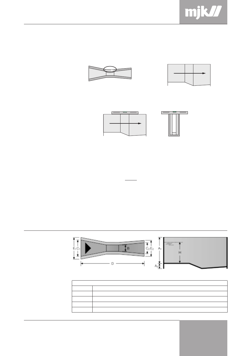
Dimensions
Size
A1
A2
B
C1
C2
D
E1
E2
2 inch
410
58
50.8
214
135
774
334
255
3 inch
610
75
76.2
259
178
914
379
298
6 inch
610
155
152.4
397
394
1525
517
514
9 inch
762
143
228.6
575
381
1626
695
501
12 inch
914
270
304.8
845
610
2867
965
730
All measurements in mm
The flume is designed to be moulded into concrete. Concrete with a low content of water
should be used - a plasticizer can be mixed in.
1 Position the flume correctly in relation to the flow direction. Observe the flow direction as
indicated with an arrow on the top edge of the flume:
2 Fix the flume in the shuttering and make sure it is precisely leveled in both directions.
3 Cover inlet and outlet with plywood board or similar and put a piece of wood inside the
flume to support its sides.
4 Fill concrete into the shuttering until it lies a little higher than the bottom of the flume and
vibrate, so that the concrete becomes well distributed under the flume.
NB! Let the concrete harden before filling the sides of the shuttering, so the flume will be
firmly secured in the concrete.
5 Fill both sides with concrete. Do not vibrate the concrete at the sides of the flume!
6 A 10 mm elastic infill along both sides of the flume is recommended to prevent water
penetration and possible frost fracture.
7 Mount the sensor bracket so that the sensor will be located at a distance ‘L’ from the
flume throat as explained on the front page.
Flow direction!
Levelled both laterally and longitudinally!
Sensor distance