Aquavar spd quick start up guide – Xylem IM216 R2 S-Drive Quick Start Up Guide User Manual
Page 2
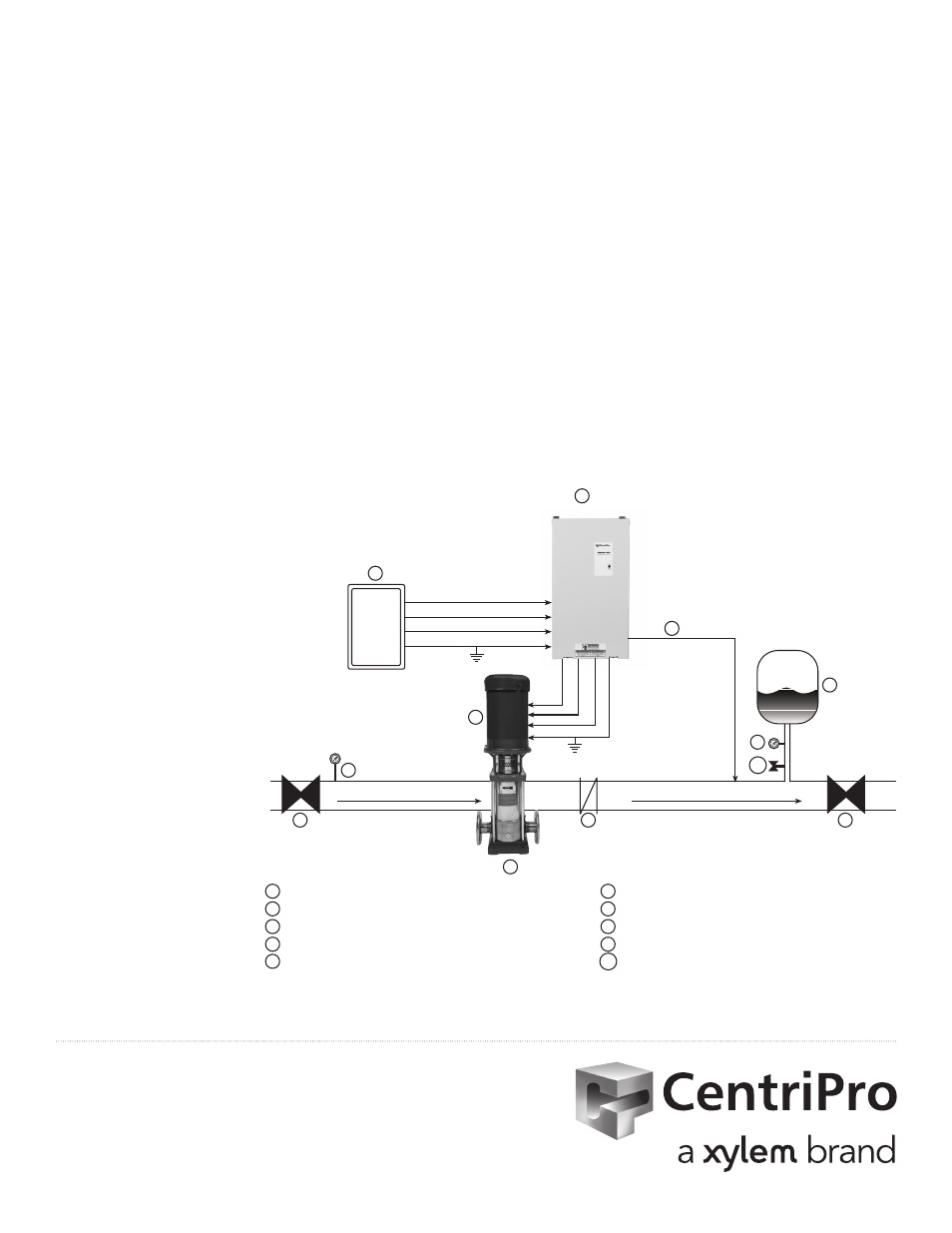
FLOW
AIR
4
8
6
3 PHASE OUTPUT
TO MOTOR
5
1
2
SUCTION
3
8
9
7
1 SPD CONTROLLER
6
AIR DIAPHRAGM TANK
2 FUSIBLE DISCONNECT
7
3 PHASE MOTOR
3 CENTRIFUGAL PUMP
8
GATE VALVE (BALL VALVE)
4 CHECK VALVE
9
PRESSURE GAUGE
5 PRESSURE TRANSDUCER (CABLE ASSEMBLY) 10 PRESSURE RELIEF VALVE
NOTES: For single phase input power, use L1 and L3 terminals and adjust motor overload switches
to 50% of controller rating or lower.
9
T1
T2
T3
L1
L2
L3
SUPPLY POWER
GND
GND
10
Goulds is a registered trademark of Goulds Pumps, Inc. and is used under license.
© 2012 Xylem Inc. IM216 Revision Number 2 February 2013
Xylem Inc.
2881 East Bayard Street Ext., Suite A, Seneca Falls, NY 13148
Phone: (866) 325-4210 Fax: (888) 322-5877
www.centripro.com
Aquavar SPD Quick Start Up Guide
Step 1: Mount drive on secure wall or support beam using 4 screws. Ensure drive is well ventilated. Leave at least 8" of free space
around the controller for cooling. Plug conduit holes not used.
Step 2: Measure site voltage phase to phase and phase to ground; verify if the incoming voltage is single or three phase 230 or
460 volt supply. Models SPD2XXXX require 230V input voltage. Models SPD4XXXX require 460V input voltage.
Step 3: Provide a dedicated fused disconnect (item #2 above) or circuit breaker rated for drives input amps. No other equipment
should be used for this disconnect. Use fast acting class T fuses.
Step 4: Connect wire from input power supply to L1, L2, L3 and GND. NOTE: For single phase supply power, wire to L1 and L3 and
adjust overload switches for 50% of drive current rating. Ensure you have a solid ground from the building or site. Ensure
the ground is continuous between the service entrance and the controller. Ensure there is at least 8" between the input
wires and any other wires.
Step 5: Ensure you have a three phase motor. Connect motor leads to T1/U, T2/V, T3/W and GND. Ensure the ground is
continuous between the controller and the motor. To change rotation, swap any two motor leads T1/U, T2/V or T3/W.
Ensure there is at least 8" between the output wires and any other wires.
Step 6: Plumb pressure transducer in straight piece of pipe downstream of last check valve in system. Do not install the pressure
transducer or pressure tank where freezing can occur. If pressure transducer is placed in grounded metal piping,
disconnect the drain wire in the pressure transducer cable from the controller chassis.
Step 7: Pre-charge bladder tank to 20 psi below your system pressure. Tank capacity should be at least 20% volume of max pump
GPM.
Step 8: Set the Motor
Overload Setting
Switches. Choose a
setting that is equal
to or less than the
motor’s SFA rating.
Step 9: Factory pressure
setting is 50psi
when used with a
300psi transducer.
Press and hold INC
or DEC button to
adjust pressure while
pump is running.
Ensure drive goes
into stand-by mode
(solid green light/
pump off) to save
pressure setting.
NOTE: Do not connect
power to
CONTROL
TERMINALS.
Connect only non-
powered switch
contacts to these
terminals.