Xylem IM127 R03 Single Phase Sump, Effluent and Sewage User Manual
Page 6
6
Reset the Alarm circuit, place pump switch(es) in the
Automatic position and Control Switch in ON position.
The system is now ready for automatic operation.
Explain the operation of the pumps, controls and alarms
to the end user. Leave the paperwork with the owner or
at the control panel if in a dry, secure location.
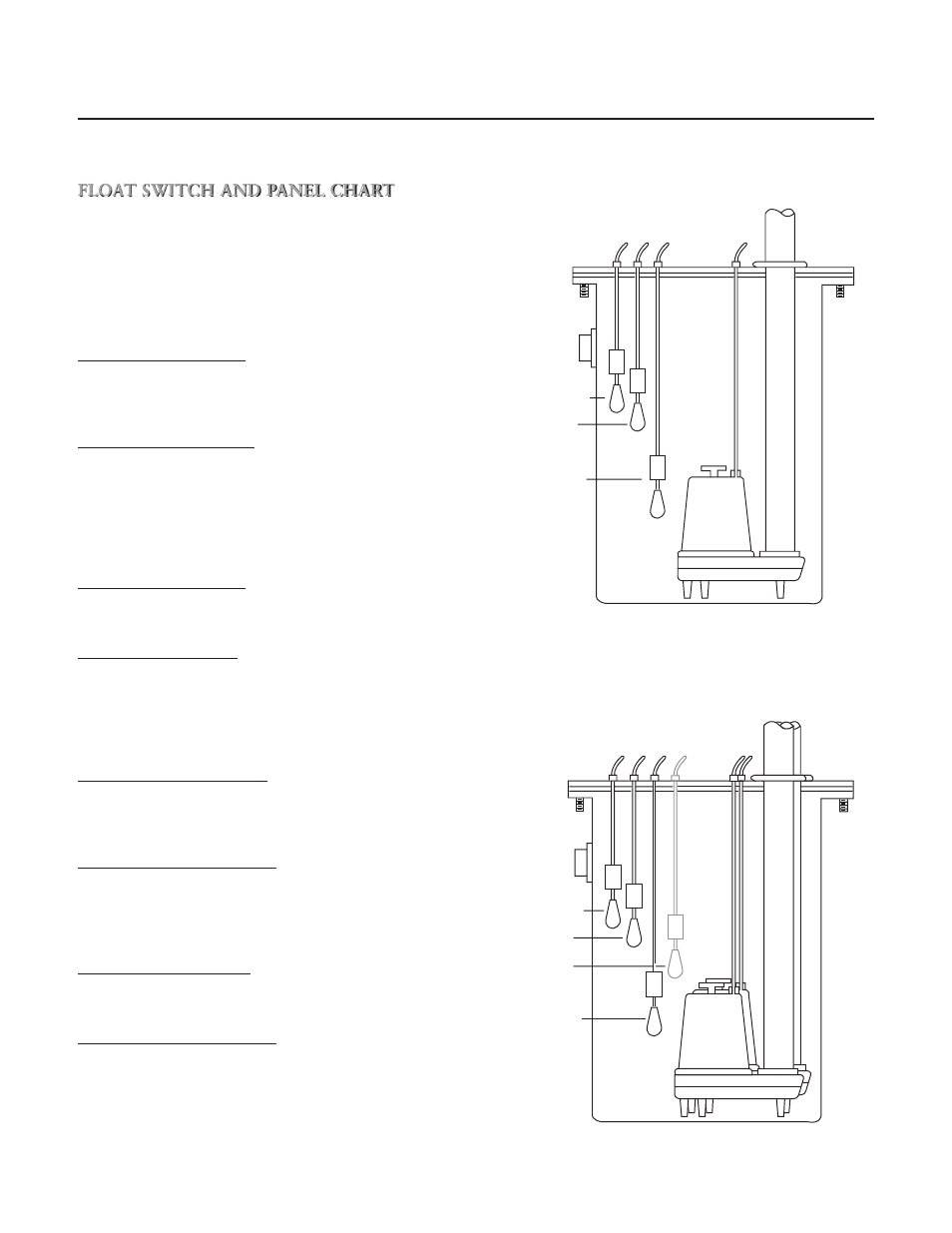
FLOAT SWITCH AND PANEL CHART
The purpose of this chart is to show the required switch
quantities and the function of each switch in a typical
wastewater system. The quantities required vary de-
pending on the switch type, single-action or wide-angle.
Switch quantities also vary by panel type: simplex with
and without alarms, and duplex with alarms.
Duplex Panels using single-action switches:
Three Float Panel Wiring
SW1
Bottom
Pumps Off
SW2
Middle
1st Pump On
SW3
Top
2nd Pump & Alarm On
Four Float Panel Wiring ➁
SW1
Bottom
Pumps Off
SW2
2nd
1st Pump On
SW3
3rd
2nd Pump On
SW4
Top
Alarm On
Duplex Panels using wide-angle switches:
Three Float Panel Wiring
SW1
Bottom
1st Pump On/Both Off
SW2
Top
2nd Pump & Alarm On
Four Float Panel Wiring
SW1
Bottom
1st Pump On/Both Off
SW2
Middle
2nd Pump On
SW3
Top
Alarm On
Simplex Panel using single-action switches:
Simplex Panel with Alarm ①
SW1
Bottom
Pump Off
SW2
Middle
Pump On
SW3
Top
Alarm On/Off
Simplex Panel with No Alarm
SW1
Bottom
Pump Off
SW2
Top
Pump On
Simplex Panel using wide-angle switches:
Simplex Panel with Alarm
SW1
Bottom
Pump On/Off
SW2
Top
Alarm On/Off
Simplex Panel with No Alarm
SW1
Pump On/Off
Inlet
Alarm SW3
Pump On SW2
Pump Off SW1
Discharge
Inlet
Alarm SW4
Lag Pump On
SW3
Pump Off
SW1
Discharge
Lead Pump On
SW2
Simplex ➀
Duplex ➁