Xylem AC5659A G&L Pumps Series A-C 8100 Base Mounted Centrifugal Pumps User Manual
Page 27
27
Remove coupler guard (see separate instructions on page
29) and disconnect coupler.
Remove external tubing (1-939-9) if supplied.
2. Loosen but do not remove main joint capscrews (2-904-1
and 2-904-2). Insert a screwdriver or pry bar into the slots
between the upper and lower casing halves – separate
joint.
3. Remove all casing main joint capscrews and dowels
(2-916-1), lift off the upper casing half.
4. Tap the stuffing boxes with a soft-headed hammer to
break the seal between the stuffing box and lower casing
half, and lift the rotating element out of the lower casing.
NOTE: A spare rotating element can be installed at this
point (See Figure 26).
5. Remove four capscrews (3-904-9) from each bearing
housing (3-025-3 and 3-025-4) and remove the bearing
housings from the shaft.
6. Remove snap ring (3-915-4) (or locknut and lockwasher
on pumps built after 1991) from the outboard end of the
shaft and, using a puller, remove the bearing (3-026-4)
from the shaft. Remove the drive end bearing in the same
manner.
NOTE: Snap ring is not used on drive end bearing.
IMPORTANT: Do not reuse the ball bearings.
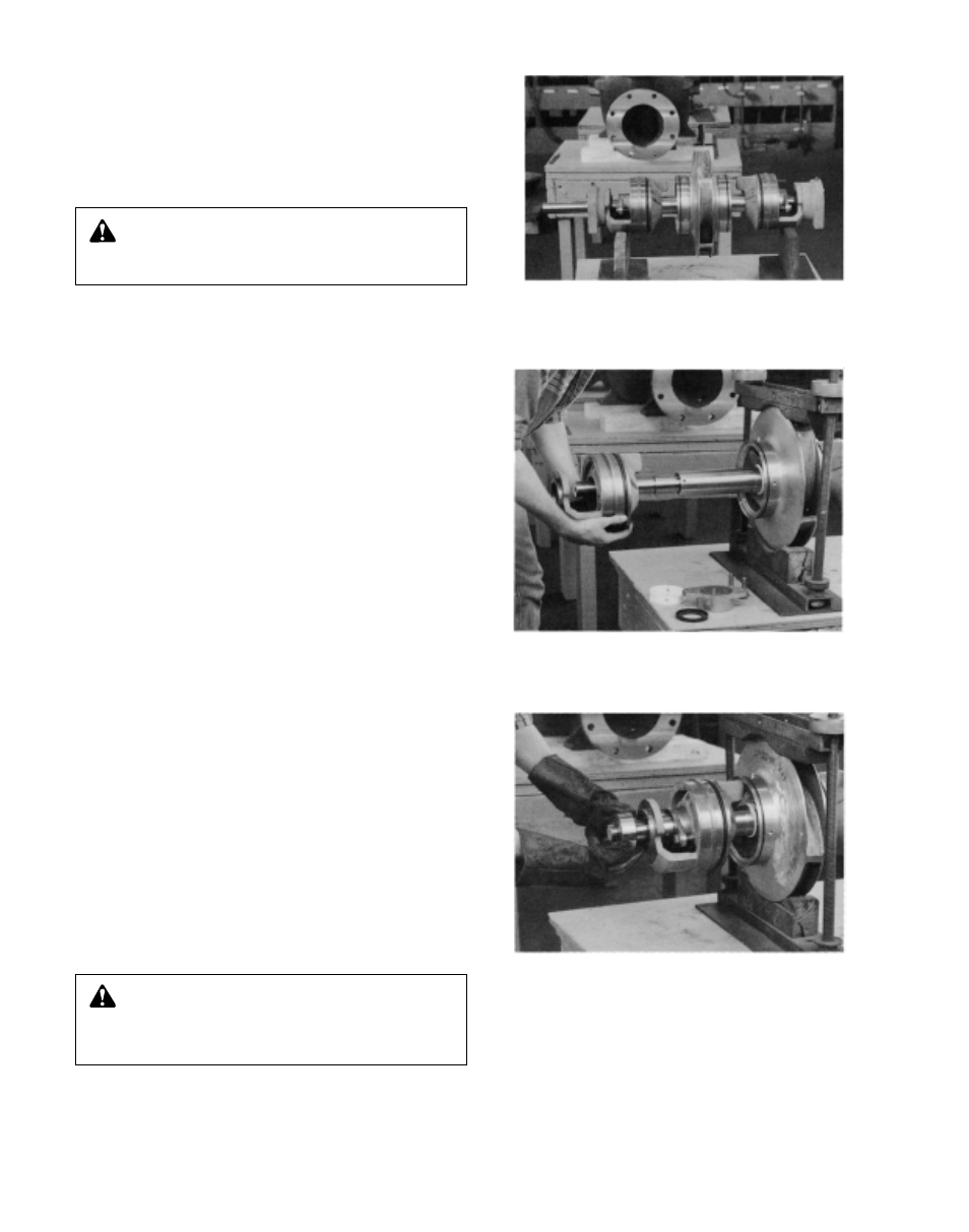
7. Slide stuffing boxes (3-073-9) off of the shaft, working
deflector ring (3-136-9) off the shaft at the same time (See
Photo 25).
8. Drive oil seal (3-177-9) from the stuffing box.
9. Remove the two gland bolts, gland halves and packing
from each stuffing box.
10. Remove two casing rings (3-003-9) from the impeller
(4-002-0) and remove “O” ring (3-914-2) and locating pin
(3-943-9) from each casing ring (See Photo 25).
11. Loosen set screw (3-902-3) in shaft nut (3-015-9) and
remove the nut. On pumps built after 1991, remove
O-rings from counterbore in shaft sleeves.
12. Remove shaft sleeve (3-009-9) and impeller (4-002-0).
NOTE: Apply heat uniformly to the shaft sleeve to loosen
the sealant between the shaft and sleeve. DO NOT HEAT
ABOVE 300°F. To further assist in removing the sleeve,
hold the shaft vertically and drop it on a block of wood.
The impeller weight should force both the impeller and
sleeve from the shaft.
CAUTION: Excessive Pressure Hazard
Make certain the internal pressure is relieved before
continuing. Failure to follow these instructions could result
in serious personal injury or death and property damage.
CAUTION: Extreme Temperature and/or
Flying Debris Hazard
Eye protection and gloves required. Failure to follow these
instructions could result in property damage and/or moder-
ate personal injury.
Photo 26 – Installing Shaft Bearing
Photo 24 – Rotating Element
(Packing Installed)
Photo 25 – Removing Stuffing Box