Xylem 9100 Series Base Mounted Centrifugal Fire Pumps AC8585 REV.C User Manual
Page 31
CAUTION:
31
DO NOT EXCEED 275°F.
CAUTION:
These are precision, high quality bearings.
Excercise care at all times to keep them clean and
free from foreign matter.
9. Press bearing isolators (1-333-1) in each
bearing cover. (See Figure 16) Install
gaskets (3-409-9) on each bearing cover.
10. Slide bearing covers (3-018-3, -4) on the
shaft. Install snap rings (3-915-9). Install
thrust washer (3-078-9) on the outboard
end.
For ease of assembly and protection of
rubber parts while sliding rubber parts
onto shaft, cover O-ring groove, keyways,
and threads with electric tape.
NOTE: Inboard bearing cover (3-018-3) is
approximately 1/4 inch less in width than the
outboard bearing cover (3-018-4). This is the
only dimensional difference.
11. Press heated bearing (3-026-2) on shaft
against snap ring or thrust washer. Install
locknut (3-516-4) and lockwasher (3-517-
4) on outboard end. Make certain locknut
is secured and then bend over tab on
lockwasher.
PUMPS WITH GREASE LUBRICATION
12. Cool bearings at room temperature and
coat with 2 or 3 ounces of a
recommended grease.
13. Press bearing isolator (1-333-1) in inboard
bearing housing and install oil seal (3-177-
4) in outboard bearing housing.
14. Slide bearing housings (3-025-2) onto
shaft (3-007-0) over bearings (3-0262).
15. Assemble bearing cover to bearing
housing with two cap screws (3-904-9).
16. Replace pump coupling half and key (3-
911-2).
17. Assemble rotating element in lower half
casing (2-001-8). Correctly locate casing
ring pins (3-943-9) in casing main joint
slot.
NOTE: Sliding inboard bearing housing
toward coupling prior to assembling rotating
element in casing will ease assembly.
18. Bolt outboard bearing housing in place. Be
sure that both housing are seated properly
in lower half casing.
19. Bolt inboard bearing housing in place.
20. Clean the gasket surfaces of the casing.
Apply Scotch 3M-77 spray adhesive or
equivalent to the lower half of the casing.
21. Within one minute of spraying, set the
gaskets (2-123-5, -6) in place on the lower
half casing, align the holes in the gaskets
with the holes in the casing and press the
gaskets firmly against the lower half
casing face in the area coated by the
adhesive.
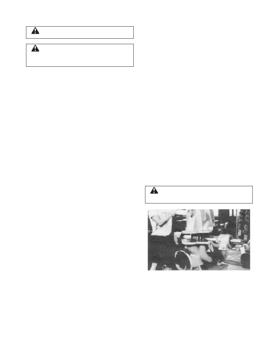
22. Lower upper half casing (2-001-7) into
place (See Figure 17) and locate using the
taper dowels (2-916-9) and install casing
main joint bolts (2-904-9). The casing joint
bolts should be tightened to the following
torques: 300 ft-lb minimum for .75"-10
Ferry Cap Counter-bore screws (Grade 8),
400 ft-lb minimum for 1.0"-8 Ferry Cap
Counter-bore screws (Grade 8). Bolt
torquing pattern is shown in Figure 11.
Before tightening bolts, be sure taper
dowels are seated properly in reamed
holes.
CAUTION:
Double check rotation of pump before
installing the upper half casing. (Refer to figure 10)
FIGURE 17 - LOWERING CASING COVER
ONTO LOWER HALF
NOTE: Torque values are essential in
obtaining proper gasket compression so no
leakage can occur at main joint.
23. Rotate shaft by hand to assure that it turns
smoothly and is free from rubbing and
binding.
24. Cut full rings of 5/8 inch square packing so
that ends butt, leaving no gap between