7 troubleshooting – Analytical Industries AII-2000 M Oxygen Analyzer User Manual
Page 15
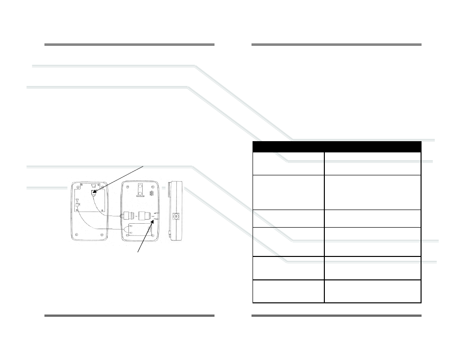
6.3.2 Procedure AII 2000HC - Integral Sensor
1. Tools required: small bladed screwdriver.
2. Place the device face down on a flat surface.
3. Remove the two (2) screws from the upper corners of the rear of the
device.
4. Move the tripod up, remove the battery compartment cover (see Battery
Replacement) and remove the two (2) screws located on either side.
5. Pull the rear section up ¼”-½”, turn it over and lay it next to the other
section.
6. Locate the white connector at the end of the four (4) wires running from
the sensor (the cylinder with the white label) to the top of the PCB.
7. With your left for finger and thumb, grasp the sides of the back end of the
white connector where it is soldered to the PCB.
8. With your right fore finger and thumb, grasp the sides of the section of
the white connector where the four (4) wires from the sensor terminate.
9. Separate the connector - hold the white connector section your left hand
while gently pulling and wiggling the white connector section with your
right hand until it unlocks.
10. The oxygen sensor inserts into an adaptor (identified by a round recess
with a cylindrical hose adapter in the center) that slides into grooves
molded into the side of the case.
11. Hold the rear section of the case down, grasp the square edges of the
adaptor, lift up (lift straight up so as not to strip the grooves molded into
the adaptor and case) and remove the adaptor and oxygen sensor as a
single component.
26
12. Once the adapter and old sensor have been removed from the case, hold
the label of the sensor, again grasp the square edges of the adaptor and
pull – to separate the old sensor from the adaptor.
13. Remove the new oxygen sensor from the plastic shipping container.
14. Install the new oxygen sensor by reversing steps 12 through 3.
15. Calibrate the device after replacing the oxygen sensor.
7 Troubleshooting
If the recommended corrective action does not resolve the problem return the
device to the factory for service.
27
Symptom
Corrective Action
Device appears to be physi-
cally damaged
Turn device ON – if it successful passes
START-UP TEST and calibrates – proceed.
No digital display when ana-
lyzer is turned ON
Install battery
Replace battery
Check battery polarity
Check and/or clean battery contacts
Battery symbol on LCD display
Replace battery and calibrate device
LCD display reads 00.0
Install sensor
Check electrical connections
Assure electrical connections are dry
No response to keypad com-
mand
Replace battery
Cannot turn device OFF
Calibration routine in process – escape or
wait until completed