Hotpoint Ariston PK 750 X-HA User Manual
Page 20
GB
20
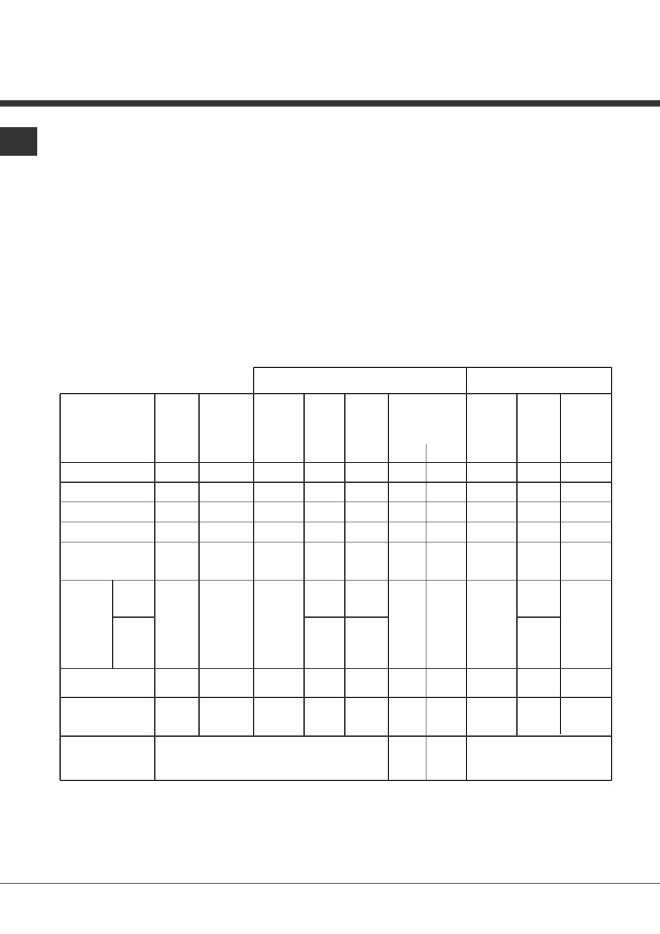
Table 1 Liquid Gas Natural Gas
Burner Diameter Thermal Thermal By-pass Nozzle Flow* Thermal Nozzle Flow*
power power 1/100 1/100 (g/h) power 1/100 (l/h)
kW kW kW
(p.c.s.*) (p.c.s.*) (p.c.s.*)
(mm) Reduced Nominal (mm) (mm) *** ** Nominal (mm)
Supply pressures
Nominal (mbar)
Minimum (mbar)
Maximum (mbar)
28-30
20
35
37
25
45
20
17
25
Fast (R)
Semi Fast (S)
Auxiliary (A)
Triple Crown (TC)
100
75
55
130
0.70
0.40
0.40
1.50
3.00
1.65
1.00
3.30
39
28
28
61
86
64
50
65x2
218
120
73
240
214
118
71
236
3.00
1.65
1.00
3.30
116
96
79
99x2
286
157
95
314
Double flame
(DCDR internal) (1)
30
0,30
0,90
27
44
65
64
0,90
72
86
Double
flame (1)
(DCDR
internal)
(DCDR
external
2 nozzle)
130
1,50
3,60
27
44
262
257
3,60
72
343
55
60x2
100x 2
Burner and nozzle specifications (for 60 cm and 65 cm versions only)
(1) For single-control DRDA (DCDR) burner only
(2) For dual-control DRDA (DCDR) burner only
*
At 15°C and 1013 mbar - dry gas
**
Propane P.C.S. = 50.37 MJ/Kg
***
Butane P.C.S. = 49.47 MJ/Kg
Natural P.C.S. = 37.78 MJ/m³
Double Flame
(DCDR Internal) (2)
Double Flame
(DCDR External)
2 nozzle (2)
30
130
0.40
1.50
0.90
3.60
27
55
44
67x2
65
262
64
257
0.90
3.60
72
100x2
86
343
5. Once the adjustment has been made, replace the seals
on the by-passes using sealing wax or a similar
substance.
6. In the event of discrete-adjustment knobs with
LED visualisation, turn the knob to the minimum
power setting them remove it and intervene on the
adjustment screw located near the tap pin.
7. Minimum setting adjustment of the DRDA (DCDR)
burner with discrete adjustment and LED
visualisation:
•
To adjust the outer ring, turn the knob anti-
clockwise to the minimum power position.
•
To adjust the minimum power setting of the
inner ring, turn the knob clockwise to the minimum
power position.
•
Remove the knob and intervene on the
adjustment screw located near the tap pin.
! If the appliance is connected to liquid gas, the regulation
screw must be fastened as tightly as possible.
! Once this procedure is finished, replace the old rating
sticker with one indicating the new type of gas used.
Stickers are available from any of our Service Centres.
! Should the gas pressure used be different (or vary
slightly) from the recommended pressure, a suitable
pressure regulator must be fitted to the inlet pipe (in order
to comply with current national regulations).