Product diagrams installation – Net Optics Multi-Station Power Supply User Manual
Page 8
Multi-Station Power Supply
4
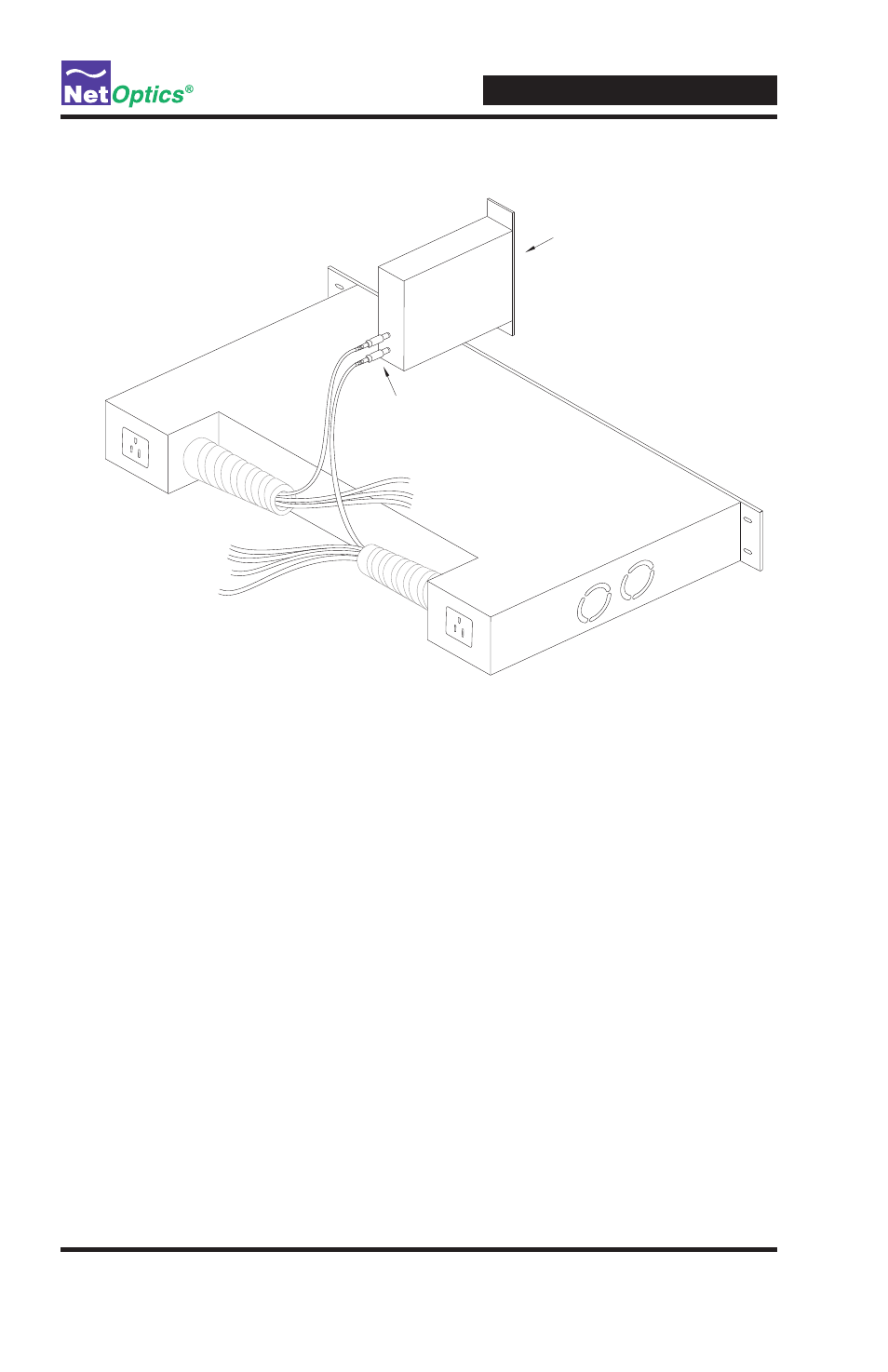
Figure 4: Connecting Power to Taps
10/100 Ethernet Tap
Dual Power for
Redundancy
DC connector leads
DC connector leads
Power 2
Power 1
Product Diagrams
Installation
To install the Multi-Station Power Supply, you simply need to connect the input
power and plug the DC output connector leads into supported Net Optics de-
vices . Details of these procedures are given in the following sections . You can
make the connections in any order: The input power can be connected either
before of after the outputs . Connections can be made and removed while the
unit is under power .
To disconnect the unit, simply unplug or disconnect the power cords from the
chassis, and the DC output connector leads from the Net Optics devices . The
inputs and outputs can disconnected in any order; however, for the DC model,
the earth grounds should be left in place as long as any other connections are
present .