Input/output wiring, Page 15, P.i.p.–amcb – Crown Audio P.I.P.-AMCb User Manual
Page 15
P.I.P.–AMCb
Page 15
Input/Output Wiring
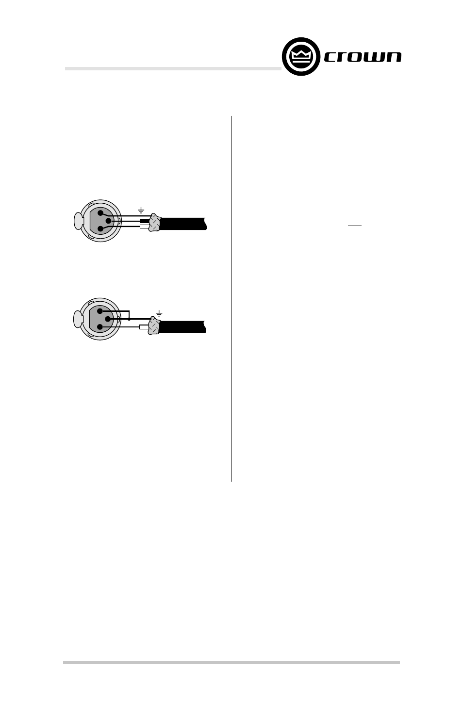
A balanced mono input is provided
via a female 3-pin XLR connector
where pin 1 is ground, pin 2 is
noninverting, and pin 3 is inverting.
Figures 3.11 and 3.12 illustrate this:
Fig. 3.11 Balanced Input Wiring
Fig. 3.12 Unbalanced Input Wiring
The “daisy chain” output is a bal-
anced output. It can be programmed
to pass low-frequency signals with
compression and EQ (PROC LO),
unprocessed low-frequency signals
(LO), low-frequency signals with EQ
(EQ LO), direct signals from the in-
put (THRU), high-frequency signals
with EQ (EQ HI), unprocessed high
frequency signals (HI) or high fre-
quency signals with compression
and EQ (PROC HI). Simply select the
appropriate position for the jumper
on the daisy chain jumper block (Fig-
ure 2.1).
The ¼-inch phone jacks on
Macro-
Tech
®
amplifiers should not be used
for input while the P.I.P.–AMCb is in-
stalled but they may be used as un-
balanced “daisy chain” outputs with
loads greater than 5 kohms. If used
in this manner, the signal available at
each jack will be the actual signal
that the P.I.P.–AMCb supplies to drive
the amplifier. For example, the signal
will be equalized and compressed
based on the status of the switch and
jumper settings of the respective
channel. This provides another way
to have several amplifiers to track
one P.I.P.–AMCb.
IMPORTANT: When operating an
amplifier in either Bridge- or Parallel-
Mono modes, only Channel 1 of the
amplifier should be driven. This
means the CH2 OUT jumper should
be removed from the jumper block
(Figure 2.1).
FROM
SOURCE
INPUT
–
+
3
1
2
GND
FROM
SOURCE
INPUT
+
3
1
2
SHIELD