3 operation, 4 specifications, General – Crown Audio IQ-RPT User Manual
Page 7: Crown bus data communication, Iq-rpt crown bus signal repeater, Page 7
IQ-RPT Crown Bus Signal Repeater
®
Page 7
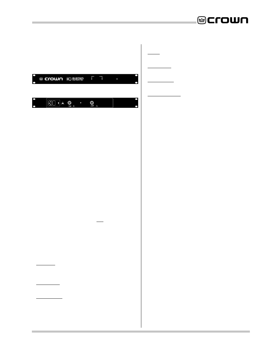
3 Operation
There isn’t much to operating an
IQ-RPT. Just plug it in
and it works. The operating environment should be free
of salt and moisture with temperatures between 32° and
158° farenheit (0° to 70° celsius).
POWER
INPUT
OUTPUT
STATUS
AC VOLTS: 100-120 AMPS: .25 50-60 Hz
AC VOLTS: 220-240 AMPS: .25 50-60 Hz
CROWN BUS
IN
CROWN BUS
OUT
OUTPUT
CONTINUITY
0.25A 250V
1
2
1
2
3
GND
CAUTION
: TO PREVENT ELECTRIC SHOCK DO NOT REMOVE
TOP COVER. NO USER SERVICEABLE PARTS INSIDE. REFER
SERVICE TO QUALIFIED SERVICE PERSONNEL.
WARNING
: TO REDUCE THE RISK OF FIRE OR ELECTRIC SHOCK
DO NOT EXPOSE THIS EQUIPMENT TO RAIN OR MOISTURE
Fig. 3.1 Front view.
Fig. 3.2 Back view.
To help with troubleshooting, the Repeater provides
several indicators that are described next.
Power: This amber front panel LED lights to show that
the unit is receiving AC power.
Input Status: This green front panel LED flashes when
incoming data is received.
Output Status: This yellow front panel LED flashes when
outgoing data is sent. It does not indicate the status of
the output cabling.
Output Continuity: This red back panel LED lights when
there is a connection between the output of the Repeater
and the input of the next device on the Crown Bus. It will
not light unless current can flow in the Crown Bus output
circuit from the positive (+) output line back to the
negative (-) output line. (The negative output line is
effectively a return line to ground.) The LED will not light
if the output circuit is open, but it will light if the positive
and negative output lines are shorted.
4 Specifications
General
Connectors:
AC Mains: 115-V units supplied with a 3-blade NEMA
5-15p cord. 230-V units require a customer-supplied
IEC power cord.
Input Data: One 5-pin female Crown Bus DIN
connector.
Output Data: One 4-pin female Crown Bus DIN
connector.
Indicators:
Power: This amber front panel indicator lights when
the unit is plugged in and receiving power.
Input Status: This green front panel indicator flashes
when incoming data is received.
Output Status: This yellow front panel indicator flashes
when outgoing data is sent.
Output Continuity: This red back panel indicator shows
that the Crown Bus output lines have made a complete
circuit.
Power Requirements: 115-V units: 100 to 120 VAC, 50-
60 Hz. 230-V units: 220 to 240 VAC, 50-60 Hz.
Power Consumption:
100VAC, 50Hz:
2.4W
100VAC, 60Hz:
2.3W
120VAC, 50Hz:
3.7W
120VAC, 60Hz:
3.0W
220VAC, 50Hz:
3.0W
220VAC, 60Hz:
2.6W
230VAC, 50Hz:
3.4W
230VAC, 60Hz:
2.8W
240VAC, 50Hz:
3.8W
240VAC, 60Hz:
3.0W
Fuse: All models use 1/4 amp fuses.
Finish: Black powder-coated steel chassis and front
panel.
Dimensions: 19-inch (48.3-cm) standard rack mount
width (EIA RS-310-B), 1.75-inch (4.4-cm) height and
6.5-inch (16.5-cm) depth.
Weight: 4 lb., 6.7 oz.
Crown Bus Data Communication
Data Rate: 38.4 K baud.
Data Format: Asynchronous binary serial data with 1 start
bit, 1 stop bit, 8 data bits and no parity check.
Interface Type: Opto-isolated 20-milliamp current loop.
Operation: Half duplex.
Transmission Distance: Variable from 200 to 3,000 feet
(61 to 914 meters) depending on wire capacitance.
1,000 feet (305 meters) is typical with shielded 26 AWG
twisted pair wire.