3 installation, Input/output wiring, Page 17 p.i.p.–bp1x & p.i.p.–bp1c – Crown Audio P.I.P.-BP1 User Manual
Page 17
Page 17
P.I.P.–BP1X & P.I.P.–BP1C
Reference Manual
3 Installation
To avoid damaging the
P.I.P.–BP1, turn
off the amplifier’s power before making
any changes (the
P.I.P.–EXT acces-
sory should not be used to adjust set-
tings with the power on).
Input/Output Wiring
Both models of the
P.I.P.–BP1, have
balanced inputs and daisy-chain out-
puts. XLR connectors are supplied
with the
P.I.P.–BP1X and are wired
such that pin 1 is ground, pin 2 is non-
inverting (“hot”), and pin 3 is inverting.
(Figures 3.1 and 3.2 illustrate this.)
Some Crown amplifiers come supplied
with permanent 1/4-inch input jacks.
These should not be used for input
while the
P.I.P.–BP1, is installed but
they may be used as unbalanced
daisy chain outputs with loads greater
than 5 k ohms. If used in this manner,
the signal available at each jack will be
the channel output signal from the
PIP.
This signal is the same signal that is
sent to the amplifier to which the
PIP is
connected. This provides another way
to have several amplifiers track the
signal that one
P.I.P.–BP1 produces.
(Another is to use the daisy chain out-
puts of the
PIP.)
Fig. 3.1 Balanced Input Wiring
Fig. 3.2 Unbalanced Input Wiring
FROM
SOURCE
INPUT
–
+
3
1
2
GND
FROM
SOURCE
INPUT
+
3
1
2
SHIELD
Fig. 3.4 Installation into a
Standard P.I.P. Amplifier
P.I.P.
MODULE
BACK PANEL
OF AMPLIFIER
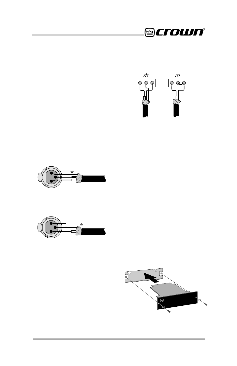
The
P.I.P.–BP1C, comes supplied with
removable barrier block connectors.
These connectors are wired with pin 1
non-inverting (“hot”), pin 2 ground and
pin 3 inverting. (See Figure 3.3.) Mat-
ing barrier block connectors are sup-
plied with the unit that are used to
attach to the interconnecting cables.
The barrier block connectors can then
be connected and disconnected eas-
ily.
Fig. 3.3 Audio Wiring
+
–
+
–
Balanced
source
Unbalanced
source