3B Scientific SW Physical Pendulum Set User Manual
Page 3
3
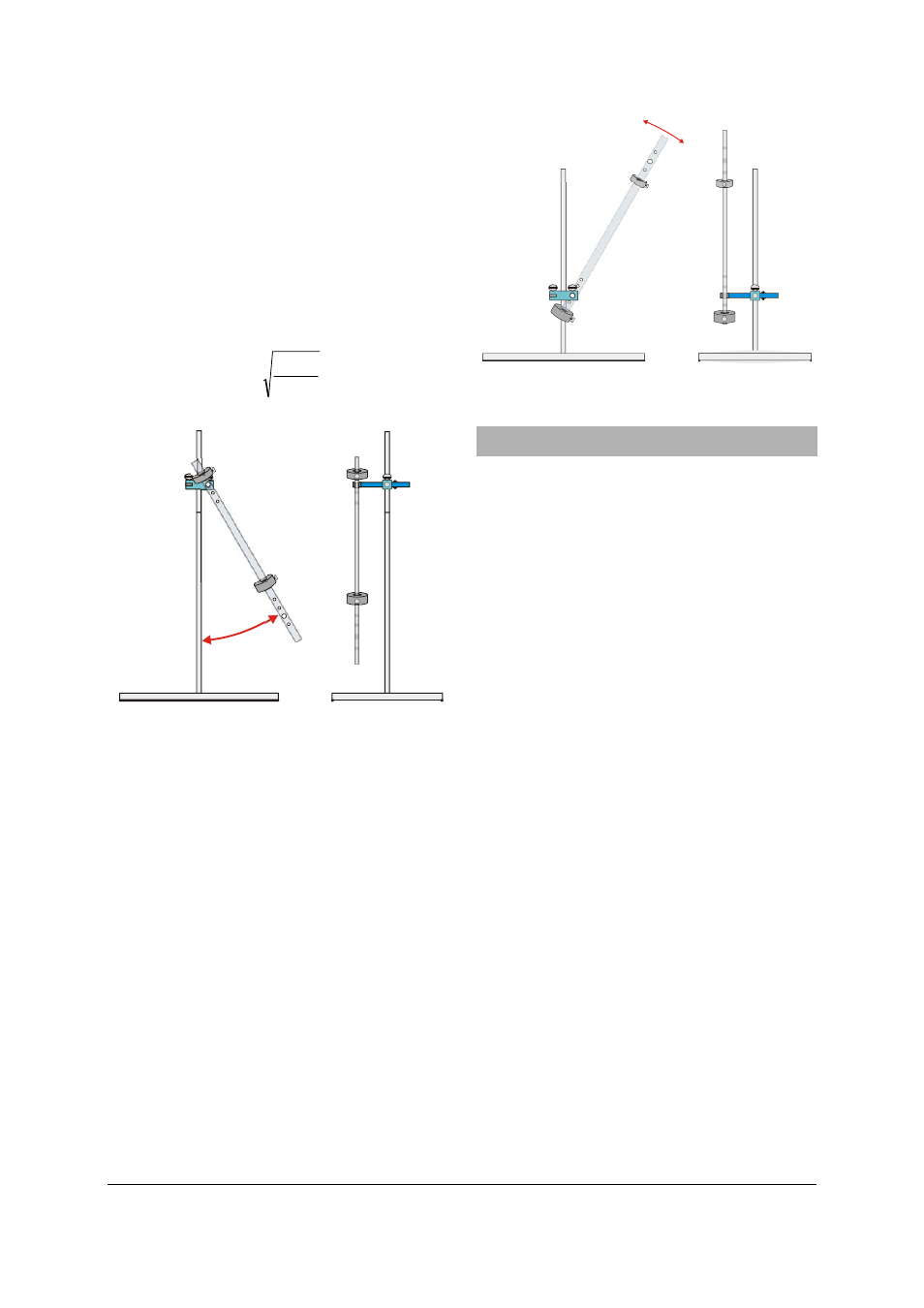
4.4 Set-up for a reversible (Kater) pendulum
•
Set up the pendulum stand as described in
4.2.
•
To set up a reversible pendulum, position a
200-g weight between the bearing holes and a
150-g weight at the top end of the pendulum.
Note:
•
Only deflect the pendulum by small angles.
If the bearing holes are l = 330 mm apart, as
long as the pendulum is correctly adjusted, the
oscillation about either bearing should have a
period T = 1.152 s (g = 9.81 m/s²).
g
l
T
⋅
π
=
2
4
Fig. 4 Set-up for reversible pendulum
4.5 Set-up for metronome pendulum
•
Set up the pendulum stand as described in
4.2.
•
Attach a 200-g weight at the bottom of the
pendulum rod with the knurled screw.
•
Attach the acrylic ring near the top of the
pendulum.
Note:
This pendulum can be used to achieve a
wide variety of periods.
By moving the large weight, the oscillating sys-
tem can be adjusted to approach an indifferent
equilibrium. Period durations are then effectively
limited only by friction at the bearings.
Fig. 5 Set-up for a metronome pendulum
5. Set-up for pendulums with sensors
5.1 General information
The following additional equipment is necessary
in order to carry out the experiments:
1 SW stand equipment set
1012849
1 SW sensors set (@230V)
1012850
or
1 SW sensors set (@115V)
1012851
1 USB oscilloscope 2x 50 MHz
1017264
1 PC, operating system Win XP, Vista, Win 7
or
1 Analog oscilloscope 2x 30 MHz
1002727
Caution:
Dynamic force sensors must not be
subjected to mechanical overloading
•
Neither sensor hook may be loaded with
more than 5N in the axial direction and 1 N
in transverse direction.
•
Be especially careful with the maximum
loading force when assembling the system
or suspending loops or springs from the
hook.
•
Make sure stand rods are firmly fitted into
the base and that all other mounting ele-
ments are also firmly fitted to the stands.
•
Do not bend the pendulum rods over the
bearings (otherwise they could break).
The force sensors can be set up with high or low
pre-tensioning of the coupling springs (by at-
taching them to two different positions on the
cross bar). This means that the distance be-
tween pendulum rod and force sensor may dif-
fer. One position allows for high amplitudes with
long pendulum swings, whereas the other pro-
vides for low bearing friction but only short pen-
dulum swings and therefore small amplitudes
are possible.