3B Scientific Premium Franck-Hertz Experiment Heater (230 V, 50__60 Hz) User Manual
Page 2
2
2. Description
The Franck-Hertz tube with its mercury filling is used
to demonstrate the quantised release of energy by
free electrons colliding with mercury atoms and to
determine that the excitation energy for the mercury
resonance line (6
1
S
0
– 6
3
P
1
) is 4.9 eV.
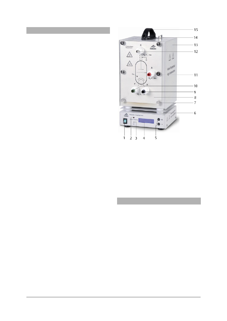
Franck-Hertz tube attached to front plate
The Franck-Hertz tube is a highly evacuated electron
tube containing mercury with its electrodes set up in
parallel planes. The electrodes consist of an indirectly
heated oxide cathode, an anode grid and a collector
electrode. In order to increase the likelihood of colli-
sions, the distance between the anode and cathode
has been made large (8 mm) in comparison to the
mean free path in a mercury atmosphere (for a tem-
perature of approx. 180°C). By contrast, the distance
between anode and collector is small. An earth ring is
located level with the anode grille to prevent distur-
bance due to background radiation. The tube is
mounted on the front plate of the heating chamber
and can be removed or exchanged. The front plate
also has ceramic-insulated sockets and a schematic
diagram of the tube. The Franck-Hertz tube is
mounted in such a way that the whole tube and its
connecting wires can all be maintained at constant
temperature. This is necessary because the density of
the mercury vapour is always determined at the cold-
est point of the tube. Leakage currents resulting from
radiation due to ion conduction in the hot glass walls
are prevented by a protective sintered alumina ring. A
fixed attenuating resistor (10 k
Ω) is inserted between
the sockets for the accelerating voltage and for the
anode of the tube. This protects the tube in the event
of excessive voltage occurring due to arcing. The volt-
age drop across this resistor can be neglected when
measurements are being made.
Heating chamber
The heating chamber serves to establish the vapour
pressure inside the Franck-Hertz tube with its mercury
filling and helps you carry out experiments with a so-
dium fluorescence tube (1000913).
It consists of a powder-coated sheet steel casing with
two viewing windows. The front plate is attached via
six knurled screws. The chamber is heated via a tubu-
lar heating element in the chamber floor. Tempera-
ture measurement and regulation is carried via an
integrated micro-controller and a PT 100 thermo-
couple. A digital temperature display allows you to
read off the temperature set-point and the actual
temperature value. The “SET” button can be used to
toggle the display between ° Celsius and ° Fahren-
heit. The “+/-” keys allow you to set the set-point for
the temperature in steps of 1 K. There is an opening
at the top with a spring clip for holding a thermome-
ter and a thermally insulated carrying handle.
The apparatus 1006794 is for operation with a mains
voltage of 115 V (±10%), and the unit 1006795 is for
operation with a mains voltage of 230 V (±10%).
2.1 Scope of delivery
1 Franck-Hertz tube with mercury filling mounted
on front-plate
1 Heating chamber without front plate
1 Instruction sheet
1 Power switch
2 Operating display
3 “SET” button
4 Display
5 “+/-” buttons
6 Thermal insulation
7 Knurled screws
8 Front plate with Franck-
8
Hertz tube attached (not
8
shown)
9 Cathode socket
10 Tube filament socket
11 Anode socket
12 BNC socket for signal
12
output
13 Heating chamber
14 Spring clip for thermometer
15 Handle
3. Technical data
Franck-Hertz tube
Filament:
4 to 12 V AC/DC
Grid voltage:
0 to 70 V
Bias voltage:
1.5 V approx.
Operating temperature: 200° C approx.
Tube dimensions:
130 mm x 26 mm diam.
Weight:
380 g approx.
Heating chamber
Mains voltage:
See back of case
Dimensions of front
opening:
230 x 160 mm² approx.
Heating power:
800 W (230 V, 50/60 Hz)
400 W (115 V, 50/60 Hz)
Maximum temperature: 300°C (230 V, 50/60 Hz)
250°C (115 V, 50/60 Hz)
Temperature constancy: ±1°C approx.
Dimensions: 335x180x165
mm³
approx.
Weight:
5.6 kg approx.