3B Scientific Photo Gate User Manual
Page 2
3B Scientific GmbH • Rudorffweg 8 • 21031 Hamburg • Germany •
www.3bscientific.com
Subject to technical amendments
© Copyright 2010 3B Scientific GmbH
5. Operation
•
Screw onto the stand rod using the arm at-
tached to the thinner of the two prongs of the
barrier and the M6 nut provided for this pur-
pose.
•
Insert the mini DIN cable into the mini DIN
connector on the broader prong of the barrier
and connect it to the 3B NETlog
TM
interface
U11300 or to digital counter U210051.
•
Activate internal light barrier mode by opening
the mechanical shutter. Subsequently, mount
and focus the device for the intended applica-
tion.
•
Activate laser light barrier mode by closing the
mechanical shutter and (roughly) focus the la-
ser light source onto the opening at the side of
the light barrier. To achieve this, mirrors may
be used to deflect the laser beam. Make fine
adjustments to the light barrier.
6. Applications
Determining the position, velocity and acceleration
of moving bodies
Determining the acceleration due to gravity g in
free fall experiments
Measuring periods of oscillating bodies
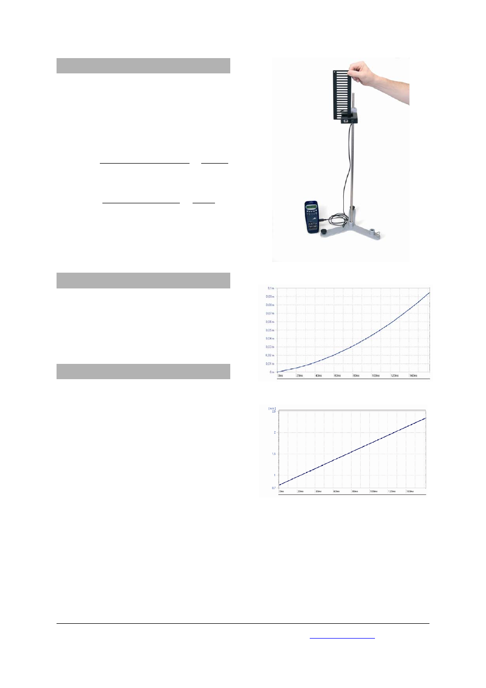
7. Sample experiment
Determining acceleration due to gravity g using
picket fence U11366
Required apparatus:
1 3B NETlog
TM
U11300
1 Light barrier
U11365
1 Picket fence
U11366
1 Stand base
U13270
1 Steel rod, length: 750 mm
U15003
1 Universal clamp
U13255
(1 Foam rubber sheet, approx. 20 x 20 cm)
•
Use the stand apparatus to fix the light barrier
at a suitable height above ground level or at
the edge of a table. If necessary, place a cush-
ioning surface (e.g. foam rubber sheet) along
the point of impact.
•
Select the digital input of the 3B NETlog
TM
inter-
face and load the free-fall experiment (tem-
plate) from the 3B NETlab
TM
software. All the
necessary settings required for evaluation are
provided by this software.
•
Conduct the experiment and analyse your
results.
Fig. 1: Measuring free fall
Fig. 2: Distance against time
Fig. 3:
Fall velocity against time