3B Scientific Sine Wave Generator User Manual
Page 2
2
2. Description
The sine wave generator is used to generate
sinusoidal voltages in a frequency range from 1Hz to
100kHz. A selector switch allows the instrument to be
used either as a sine wave generator with power
output or as a power amplifier with a pre-amplifier
stage.
The frequency can be selected over a range of 5
decades, each of which is continuously adjustable on
a scale from 1 to 10. The power amplifier has a robust
output stage and a large reserve of power. The output
stage is thermally protected and proof against short-
circuiting, and the output is current-limited.
With the mode selector switch (S3) in the microphone
position
, the socket marked E is supplied with +8V
via a 10k
Ω resistor. This bias voltage is suitable for
direct connection to an electret microphone or
carbon microphone.
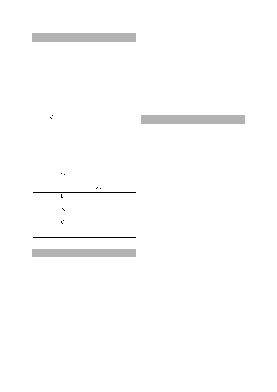
Modes of operation:
Switch Function
S1
Frequency decade switch (acts
as multiplier to the “Frequency”
adjustment)
S2
Sinusoidal voltage available at
power amplifier output –
output adjustable via
“Amplitude
“ knob
Pre-amplifier output is fed to
power amplifier output stage
S3
Input to preamplifier through
100
μF capacitor
Bias voltage (8 V, 10 k
Ω); input
to preamplifier through 1
μF
capacitor
3. Technical data
Sine wave generator with power output
Frequency range:
1 Hz - 100 kHz in 5
decades, continuously
adjustable by linear
marked dial
Frequency deviation:
< 5%
Output voltage:
0 - 6 V, adjustable
Max. output current:
10 A, short-circuit
protected
Max. output power:
16 W continuous, 30 W for
short periods
Input resistance:
100 k
Ω
Pre-amplifier
Amplification factor:
1- 250, continuously
adjustable
Input:
AC coupled, microphone
voltage switch
Max. output voltage:
10 Vpp
Max. output current:
15 mA, short-circuit
protected
Output impedance:
1 k
Ω
Power amplifier:
Voltage amplification:
0 - 8.5
Operating voltage:
12 V AC
Dimensions:
160Ч160Ч50 mm
3
approx.
Weight:
1.1 kg approx.
4. Operation
Recommended voltage supply source:
Transformer, 12 V, 25 VA
U8475430-230
or
Transformer, 12 V, 25 VA
U8475430-115
The output stage is very robust and can be relied on
to work safely in physics experiments. However, when
working with inductive loads (coils, transformers,
motors, etc.) the following precautions need to be
taken:
Switching onto an inductive load may only be done
when there is no signal (i.e., with the “Amplitude”
and/or “V” control knobs fully to the left).
Speakers can be damaged if the equipment is
switched on when there is already a signal voltage.
Therefore, before switching on, set the signal level to
zero (amplification control knob “V” fully to the left).
When the unit is operating at a high power level the
housing can become hot. Although the output stage is
not likely to be damaged by heat, under such
conditions a longer cooling period should be allowed
for.
To avoid excessive heating when operating
continuously for a long period, it is advisable to keep
the load resistance above 3
Ω.
•
Connect the mains adapter transformer to the
supply voltage input terminals.
4.1 Operation as a power amplifier with pre-
amplifier stage
•
Set switch S3 (4) to either the microphone
position (right) or the amplifier position (left) as
required, and switch S2 (8) to the pre-amplifier
position (left).
•
Turn the amplification control knob (7) fully to
the left (zero).
•
Connect the pair of output sockets (9) to the load
(e.g., low frequency speaker U8432780, horn
speaker U8432680, etc.).