3B Scientific Displacement Sensor User Manual
Page 2
2
4. Apparatus supplied
1 Displacement
sensor
1
Stand rod with thread, 120 mm
1
8-pin miniDIN cable, 1 m
1
Nylon thread, 1 m, 1 mm diam.
1 Instruction
manual
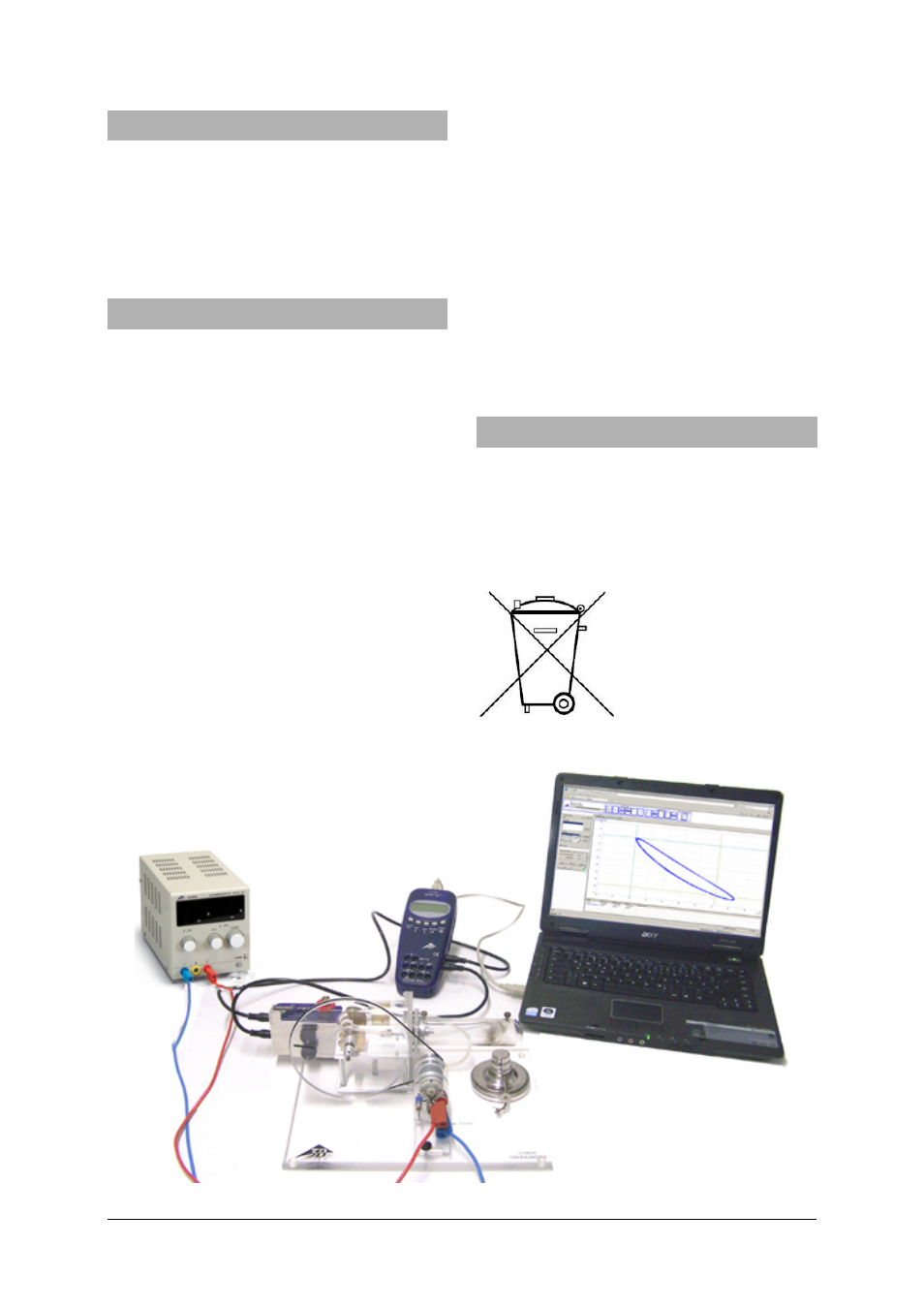
5. Example experiment
Recording a pV diagram for a G-model Stirling
motor using 3B NETlog
TM
and 3B NETlab
TM
Required equipment:
1 Stirling Engine G
1002594 / U10050
1 3B NETlog
TM
(115 V)
1000539 / U11300-115
or
1 3B NETlog
TM
(230 V)
1000540 / U11300-230
1 3B NETlab
TM
1000544
/
U11310
1 Displacement Sensor
1000568 / U11371
1 Relative Pressure Sensor
±1000 hPa
1000548 / U11323
1 Sensor Holder for
Stirling Engine G
1008500 / U11372
1 DC Power Supply
0 – 20 V, 0 – 5 A (115 V)
1003311 / U33020
or
1 DC Power Supply
0 – 20 V, 0 – 5 A (230 V)
1003312 / U33020
Experiment leads
1002843 / U138021
•
Set up the experiment as in Fig. 1.
•
Wrap the thread around the displacement sen-
sor’s pulley as in Fig. 2.
•
Turn on the 3B NETlog
TM
unit and wait for it to
automatically detect the sensor box.
•
Connect the Stirling engine’s DC motor to the DC
power supply and set an output voltage of 6 V so
that the Stirling engine operates at medium
speed.
•
Open the 3B NETlog
TM
template "Stirling engine G".
•
Only allow the Stirling motor to operate at high-
speed for short periods so as not to overstress
the displacement sensor.
6. Disposal
•
The packaging should be disposed of at local
recycling points.
•
Should you need to dispose of the equipment
itself, never throw it away in normal domestic
waste. Local regulations for the disposal of elec-
trical equipment will apply.
Fig. 1 Experiment set-up for recording the pV diagram of a G-model Stirling engine