3B Scientific Pascal's Vane Apparatus User Manual
Page 2
4
3B Scientific GmbH • Rudorffweg 8 • 21031 Hamburg • Germany • www.3bscientific.com • Technical specifications subject to change
long arm of the lever, the apparatus can be balanced to
match the force acting on the short arm. Four glass ves-
sels of different shapes
bm
but with the same base area
and height are available for experiments. A level indica-
tor
1
can be used to show the filling level of the glass
vessels. An outlet pipe
bl
at the rear of the acrylic tube
allows a hose pipe to be connected for draining liquid.
Height of vessels:
220 mm
Diameter of base:
22 mm
Total height:
350 mm
Base plate dimensions:
260 mm x 100 mm
Length of lever arms:
20 mm, 175 mm
Outlet tube:
8 mm Ø
Mass of slotted weight:
20.4 g
Weight:
0.8 kg
3. Operation
•
Set up the Pascal’s vane apparatus on a high enough
surface that liquid can drain away via the drainage
hose into a beaker.
•
On the movable scale, mark the balanced position of
the lever with no force acting (and no slotted weight).
•
Place a glass vessel into the Pascal’s vane apparatus
so that the outlet is sealed off.
•
Pour some of the liquid being used for the experi-
ment into the glass vessel and mark the filling level
with the help of the level indicator.
•
Balance the lever with the aid the slotted weight.
•
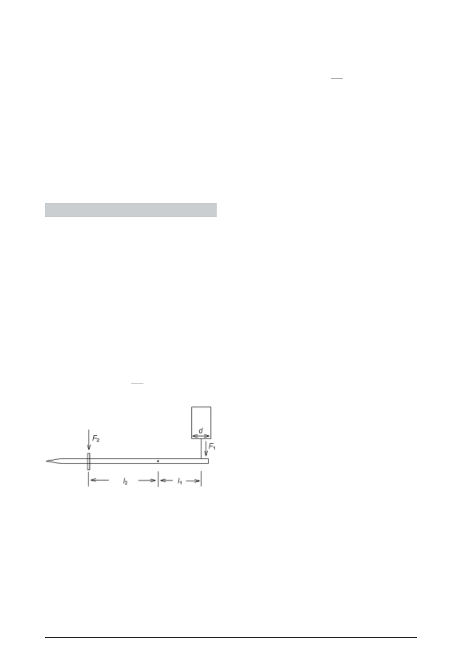
In order to determine the pressure at the bottom of
the tube, first calculate the force F
1
exerted by the
liquid column on the diaphragm by multiplying the
weight of the balancing mass F
2
by the ratio of the
lengths of the lever arm l
1
and l
2
.
I F
F
I
=
2 2
1
1
•
The pressure at the bottom of the tube is given by:
F
P
r
=
π
1
2
where r is the radius of the effective base surface of
the vessel. (Measure the diameter of the tube d = 2r
using vernier callipers
•
Lift up the glass vessel enough for the liquid to drain
through the outlet and into a beaker.
•
Thoroughly dry the apparatus to ensure that the tube
does not get dirty due to residual liquid.
3.1 Replacing rubber diaphragm and seals
•
In order to replace the rubber diaphragm and the
seals, undo the screws
9
and pull out the acrylic
tube
8
from above.
•
Unscrew the bottom, i.e. the diaphragm holder, then
remove the plastic ring and the damaged diaphragm.
•
Secure the new diaphragm with the plastic ring. Make
sure the membrane is slightly slack. If it is too taut
experimental results may be in error.
•
Screw the acrylic tube into the apparatus again.
If liquid starts to leak from glass vessels, even though
they are correctly inserted, then the seals need to be
replaced, as follows:
•
Remove the acrylic tube
8
and unscrew the bot-
tom, i.e. the diaphragm holder.
•
Grip the lips of the seals and pull them out.
•
Firmly press new sealing rings into the groove.