3B Scientific Relay User Manual
Page 2
3B Scientific GmbH • Rudorffweg 8 • 21031 Hamburg • Germany •
www.3bscientific.com
Subject to technical amendments
© Copyright 2009 3B Scientific GmbH
4. Technical data
Switching voltage:
250 V AC
220V DC max.
Switching current:
6A AC
0.12 A DC max.
Power rating:
1500 VA max.
1 mW min.
5. Operation
•
Connect the relay to the “Digital Outputs”
socket of the 3B NETlog
TM
equipment using the
supplied mini DIN lead. It responds to digital
output A.
•
Preferably use 4-mm safety leads for the re-
maining electrical connections to the experi-
ment set-up.
6. Sample experiment
Measuring the discharge of a capacitor with the
basic experiment board
1 3B NETlog
TM
U11300
1
Relay
U11368
1 Basic experiment board
U11380
Various experiment leads with 2-mm and 4-mm
plugs
Fig. 1: Measuring the discharge of a capacitor
•
Consult the instructions for the basic experi-
ment board U11380 for the electrical connec-
tions between the relay and the experiment.
•
Select one of the analog inputs (A or B) on the
3B NETlog
TM
module and follow the instructions
for the board regarding the experiment on ca-
pacitor discharge. All necessary output value
settings are specified here.
•
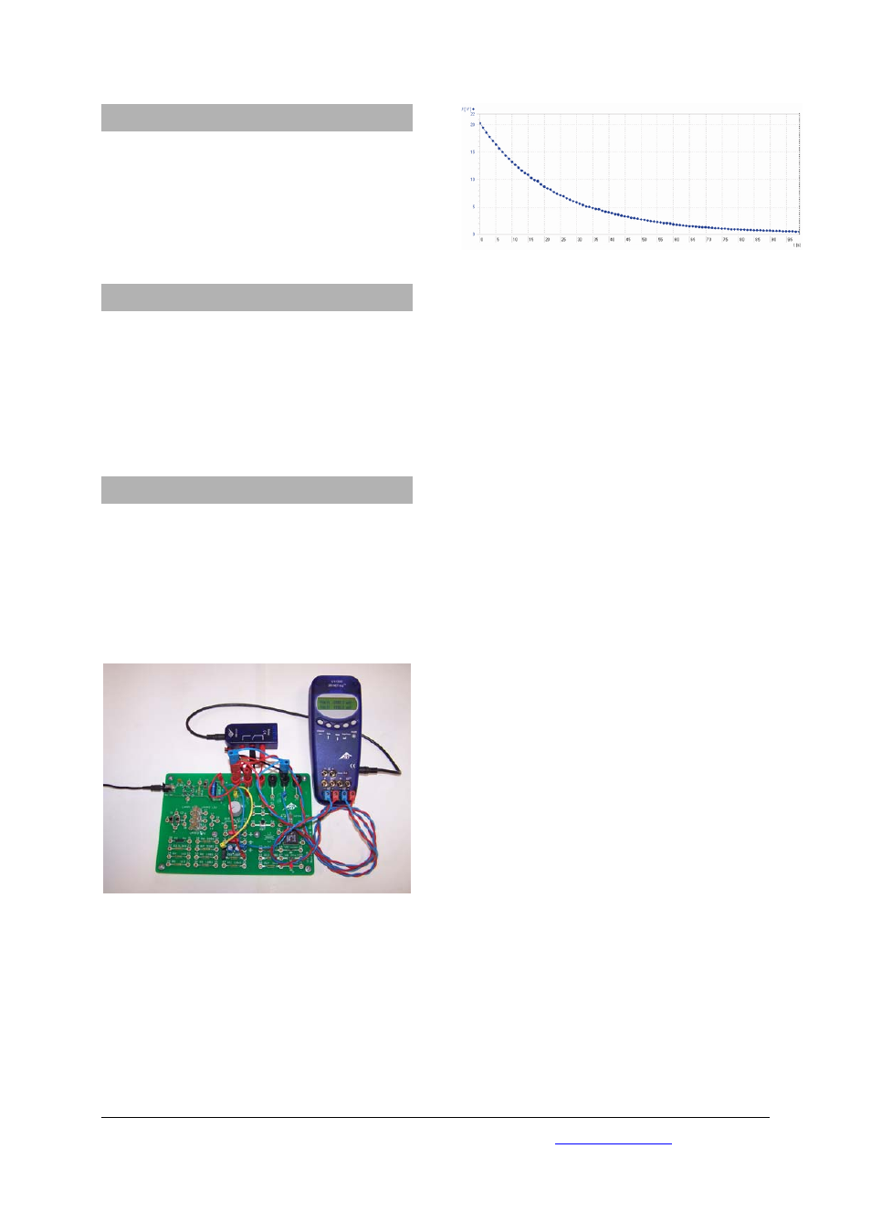
Conduct and analyse the experiment.
Fig. 2: Discharge curve of a capacitor