3B Scientific Microwave Set 9.4 GHz (230 V, 50__60 Hz) User Manual
Page 4
4
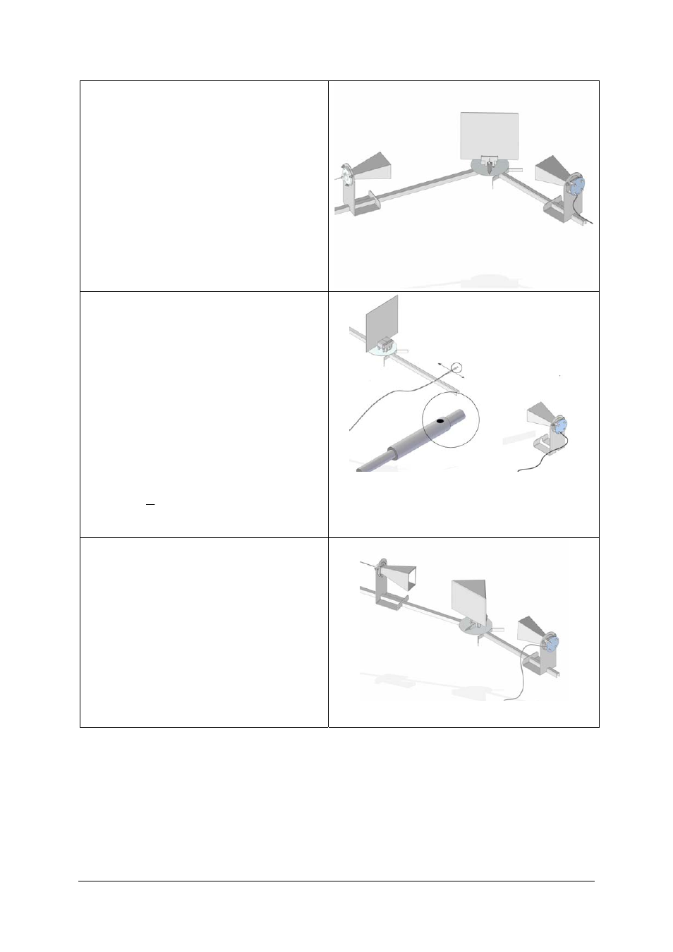
6.4 Reflection
•
Set up the basic configuration (5.1).
•
Line up the reflector plate at angles of ap-
proximately 30°, 40°, 50° and 60° with the
help of the pointer for the rails, which points
in the direction of the normal (a line perpen-
dicular to the mirror’s surface).
•
Change the angle of the long rail until the
maximum reception is attained.
•
Measure angles of incidence from the normal
(arrow).
Conclusion: an electrical conductor reflects micro-
waves. This confirms the law of reflection.
6.5 Determining wavelength of standing waves
•
Set up the transmitter and reflector plate fac-
ing each other about 50 cm apart (angle of in-
cidence 0°).
The transmitted and reflected waves are superim-
posed, resulting in a standing wave.
•
Using the microwave probe (21) (with the
marking on the special probe facing upwards)
determine the distance a between two adja-
cent minima (this corresponds to half the
wavelength).
•
Calculate the frequency f = c/
λ from the wave-
length
λ of the microwaves.
Results: a =
≈
λ
2
1,6 cm,
≈
f
9,4 GHz
6.6 Refraction
•
Set up the basic configuration (5.1).
•
Insert the stand provided for the prism (12)
into the side facing away from the arrow.
•
Put the prism (13) onto the stand and line it
up.
•
Turn the long rail until the maximum recep-
tion is attained.
Conclusion: microwaves penetrate paraffin. As the
waves pass from air to paraffin and from paraffin
to air, the speed of propagation is altered and thus
so is the direction (refraction).