3B Scientific Resistance Bridge User Manual
Page 2
2
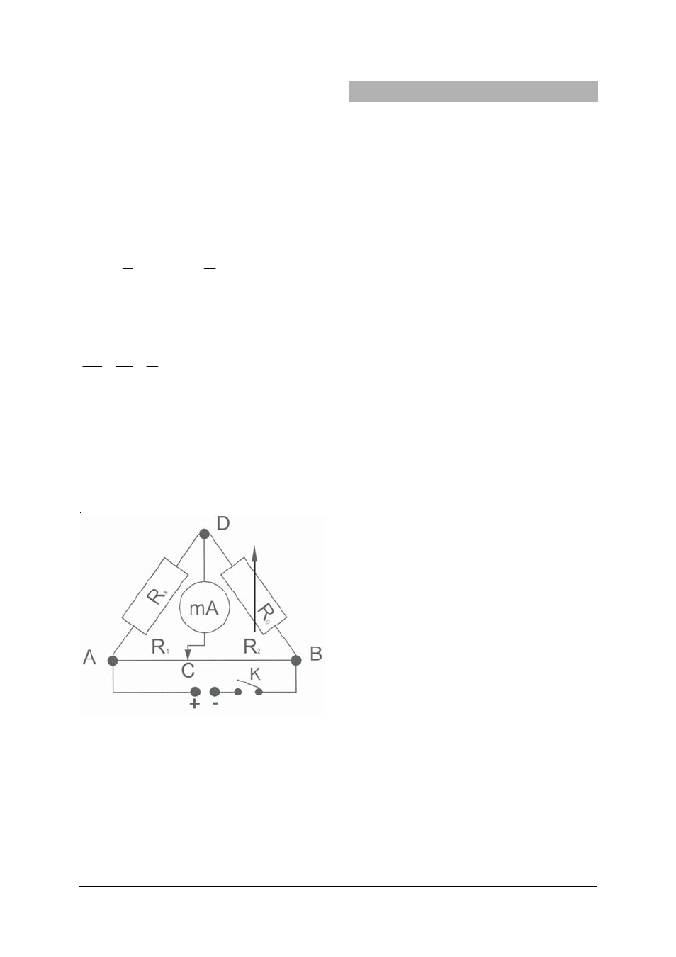
age U is applied to this circuit. The ammeter is
used to measure the current flowing between
the point D and the moveable tapping point C
located on the resistance wire.
The partial resistances of the wire R
1
and R
2
can
be varied using the slide contact on the resis-
tance wire.
Now it is important to calibrate the measurement
bridge, i.e. to adjust the slide contact so that
there is no voltage between points C and D and
thus a current no longer flows. The partial resis-
tances are:
F
l
R
1
1
⋅
ρ
=
and
F
l
R
2
2
⋅
ρ
=
whereby F is the cross-sectional area of the
wire.
For the resistance ratios the following then holds
true:
2
1
2
1
0
l
l
R
R
R
R
X
=
=
From this we can deductively compute the un-
known resistance:
2
1
0
l
l
R
R
X
⋅
=
The resistor R
0
should be selected so that upon
calibration of the bridge l
1
and l
2
are approxi-
mately equal, in order to keep the error to a
minimum.
Fig. 1
5. Sample experiments
5.1 Determining resistance in a Wheatstone
bridge circuit
Additionally required:
1 AC/DC Power Supply 12 V, 3 A (230 V, 50/60 Hz)
1002776
or
1 AC/DC Power Supply 12 V, 3 A (115 V, 50/60 Hz)
1002775
1 Zero Galvanometer CA 403
1002726
1 Resistance Decade 1 Ω 1002730
or
1 Resistance Decade 10 Ω 1002731
or
1 Resistance Decade 100 Ω 1002732
1 Incandescent lamp with socket
8 Experiment cables (500 mm)
1 Switch (optional)
• Connect up the experiment setup as illus-
trated (see Fig. 1).
• An incandescent lamp is used as the un-
known resistance.
• A voltage of 4 to 6 V is applied.
• Close switch K and slowly move the slide
contact from A to B to A again.
• At the same time observe the deflection of
the ammeter. When the pointer deflection in
the proximity of point A is zero, this means
that the value of R
0
is very high and that it
must be reduced. If the zero value is in the
proximity of point B, then the value of R
0
is
too low and must be increased.
• Select
the
R
0
value so that when the power
is switched on again the pointer of the am-
meter does not deflect when the slide con-
tact is in the middle of the wire, i.e. the
measurement bridge is calibrated.
• If there is no appropriate resistance avail-
able, use a resistor R
0
, for which the
pointer's deflection is smallest and then
carry out the calibration.
• Obtain readings of partial lengths of the
resistance wire.
• Repeat the experiment with varied voltage
levels, enter your findings in a table and
compute the resistance R
X
.
5.2 Determine the specific resistivity ρ of a
wire
• Experiment set-up according to Fig. 1, but
this time use a resistance wire with a length
from 1 to 3 m instead of the incandescent
lamp.