3B Scientific Millisecond Counter (230 V, 50__60 Hz) User Manual
Page 2
2
4. Technical data
Inputs:
Connectors: 4-mm
safety
sockets
Internal resistance
“Start” input:
2.4 k
Ω
“Stop” input:
5.6 k
Ω
Edges for “Start”
and “Stop” inputs:
Rising
Trigger threshold for
“Start” input:
Low 0...0.5 V, high 1...5 V
“Stop” input:
Low 0...1 V, High 2...5 V
Display:
Display:
4-digit LED display
Measuring range:
1...9999 ms
Resolution: 1
ms
Precision: Quartz
precision
General data:
Voltage supply:
Plug-in power supply
12 V AC, 500 mA
Dimensions:
100x75x35 mm³ approx
Weight:
400 g approx. incl. plug-
in power supply
5. Care and maintenance
• Before cleaning the equipment, disconnect it
from its power supply.
• Use a soft, damp cloth to clean it.
6. Disposal
• The packaging should be disposed of at
local recycling points.
• Should you need to dispose of the equip-
ment itself, never throw it away in normal
domestic waste. Local regulations for the
disposal of electrical equipment will apply.
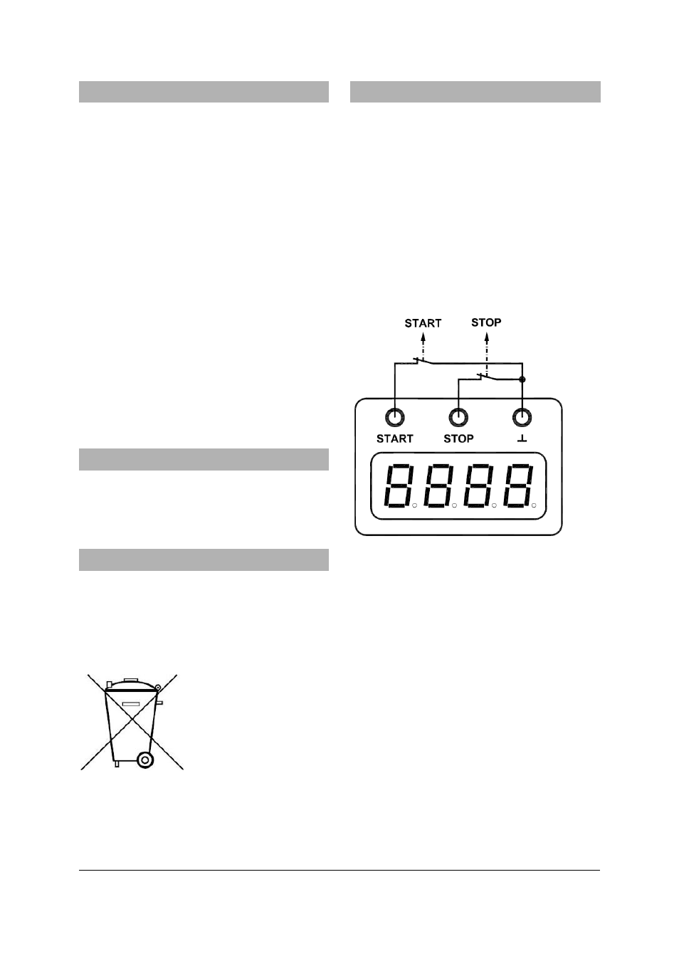
7. Operation
7.1 General operation
• Connect a 12 V AC plug-in power to the
millisecond counter (4).
Connect both inputs (1 + 2) to ground (3).
• Opening the “Start” input (1) (disconnecting
the ground) starts the measurement.
Measurement ceases as soon as the “Stop”
input (2) is opened.
The display will go back to displaying zero as
soon as both inputs are connected to ground
again.
Both inputs should be connected via normally
closed switches (see Fig. 1).
Fig. 1
Schematic diagram for connection of the
inputs
7.2 Set-up with free-fall apparatus
Additionally required:
1 Free fall apparatus
1000738
• Connect the inputs (1, 2, 3) of the millisec-
ond counter to the 3 sockets of the free-fall
apparatus making you sure you match all
the colours (see Fig. 2).
• Connect a 12 V AC plug-in power to the
millisecond counter (4).
Measurement starts as soon as the steel ball is
released from the start console and stops when
it hits the trap plate. Zero calibration is carried
out as soon as the steel ball is placed on the
start console. The timer is then ready to carry
out another measurement.