3B Scientific Analog Multimeter AM50 User Manual
Page 4
9
3.3.1 Operating mode: electrical
3.3.2 Operating mode: electrical
zero-point center
•
Set the slide switch (4) to the “
”
setting.
•
Using the rotary switch (1) select
the corresponding measurement
range “V ...”.
•
The needle should now be posi-
tioned in the center of the scale.
•
Connect the multimeter and take
a reading from the lower scale.
3.4 Measuring alternating
voltage, directly up to 300 V
~
•
Set the slide switch (4) to “
”
setting.
•
Using the rotary switch (1) select
the corresponding measurement
range “V
~
”.
•
Connect the multimeter and take
a reading from the upper scale.
•
To reduce the effects of the fre-
quency, connect the socket “
⊥
⊥⊥
⊥⊥
”
directly to ground or to the point
with the lowest potential with re-
spect to ground.
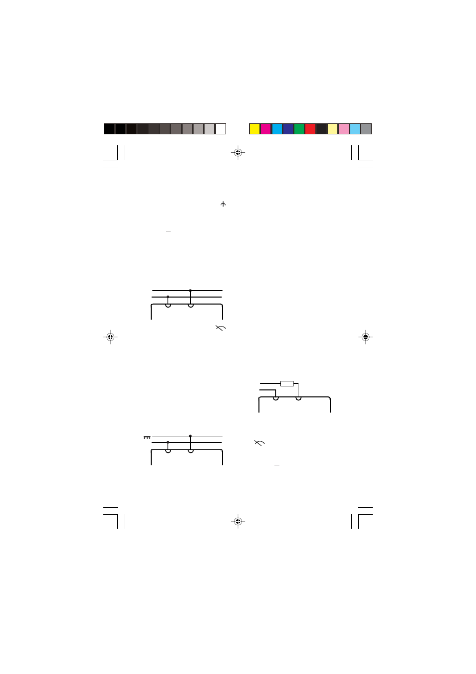
3.5 Measuring AC voltage with
superimposed DC voltage
~
•
With the aid of a capacitor (recom-
mended: 4.7 µF/630 V) it is possi-
ble to isolate DC-voltage compo-
nents in an amplifier output stage,
for example. The resultant mea-
surement error is less than 0.2%
at a measurement frequency of
50 Hz.
•
Proceed with the measurement as
stated in point 3.4.
•
Measurement of the DC voltage
components is performed as de-
scribed under 3.3.
•
To avoid overloading, the set mea-
surement range must be greater
than the initially determined DC
voltage components.
•
Caution: before switching to a low-
er measurement range both volt-
age components must be checked.
3.6 Current measurement
•
When performing current mea-
surements the multimeter must
be connected in series with the
load in the circuit, which has the
lowest potential with respect to
ground.
3.6.1 DC measurement, directly
_
+
3.6.1.1 Operating mode: electrical
zero-point left
•
Switch the slide switch (4) to the
“
” setting.
•
Using the rotary switch (1), select
the corresponding measurement
range “A ...”.
•
Connect the multimeter take a
reading from the upper scale.