3B Scientific Connector Box (230 V, 50__60 Hz) User Manual
Page 2
Elwe Didactic GmbH ▪ Steinfelsstr. 5 ▪ 08248 Klingenthal ▪ Germany ▪ www.elwedidactic.com
3B Scientific GmbH ▪ Rudorffweg 8 ▪ 21031 Hamburg ▪ Germany ▪ www.3bscientific.com
Subject to technical amendments
© Copyright 2012 3B Scientific GmbH
socket wired to Output 2 (ground) and the red
socket to Output 1, i.e. crossed over.
Apart from the two digital sensors already men-
tioned, it is also possible to connect other ana-
logue sensor boxes, such as magnetic field sen-
sors (1000558 or 1009941) or the barometer
(1000549), with the values they measure being
recorded via peripheral devices. The measure-
ments are then output in the form of an ana-
logue voltage at Analogue output 1 via the blue
and red sockets. Analogue output 2 is intended
for sensor boxes which detect two measure-
ments at once, such as the blood pressure sen-
sor (1000578). In that case, the Korotkov signal
can be read from Output 2.
When connecting analogue sensor boxes, it
should be noted that the output voltage is not
calibrated and there is no automatic matching of
measurement curves.
3. Contents
1 Connector box
1 8-pin miniDIN connecting cable, length 60 cm
1 Plug-in power supply 12 V AC / 500 mA
1009954: 115 V AC, 50/60 Hz, US plug
1009955: 230 V AC, 50/60 Hz, Euro plug
1 Instruction sheet
4. Technical data
Analogue outputs
:
4 mm safety sockets
Sensor input:
8-pin miniDIN socket
Power supply terminal
:
Coaxial power con-
nector, 5.5 x 2.1 mm
Power supply:
12 V AC, 500 mA
plug-in power supply
Dimensions: 90x30x40
mm³
Weight: 0.4
kg
5. Operation
•
Sensors such as the photo gate or laser
reflection sensor are connected to the con-
nector box via miniDIN cables.
•
Use the plug-in power supply to supply
power to the connector box.
•
Connect the counter to the black socket
(ground) of Output 2 and the red socket of
Output 1 via experiment leads.
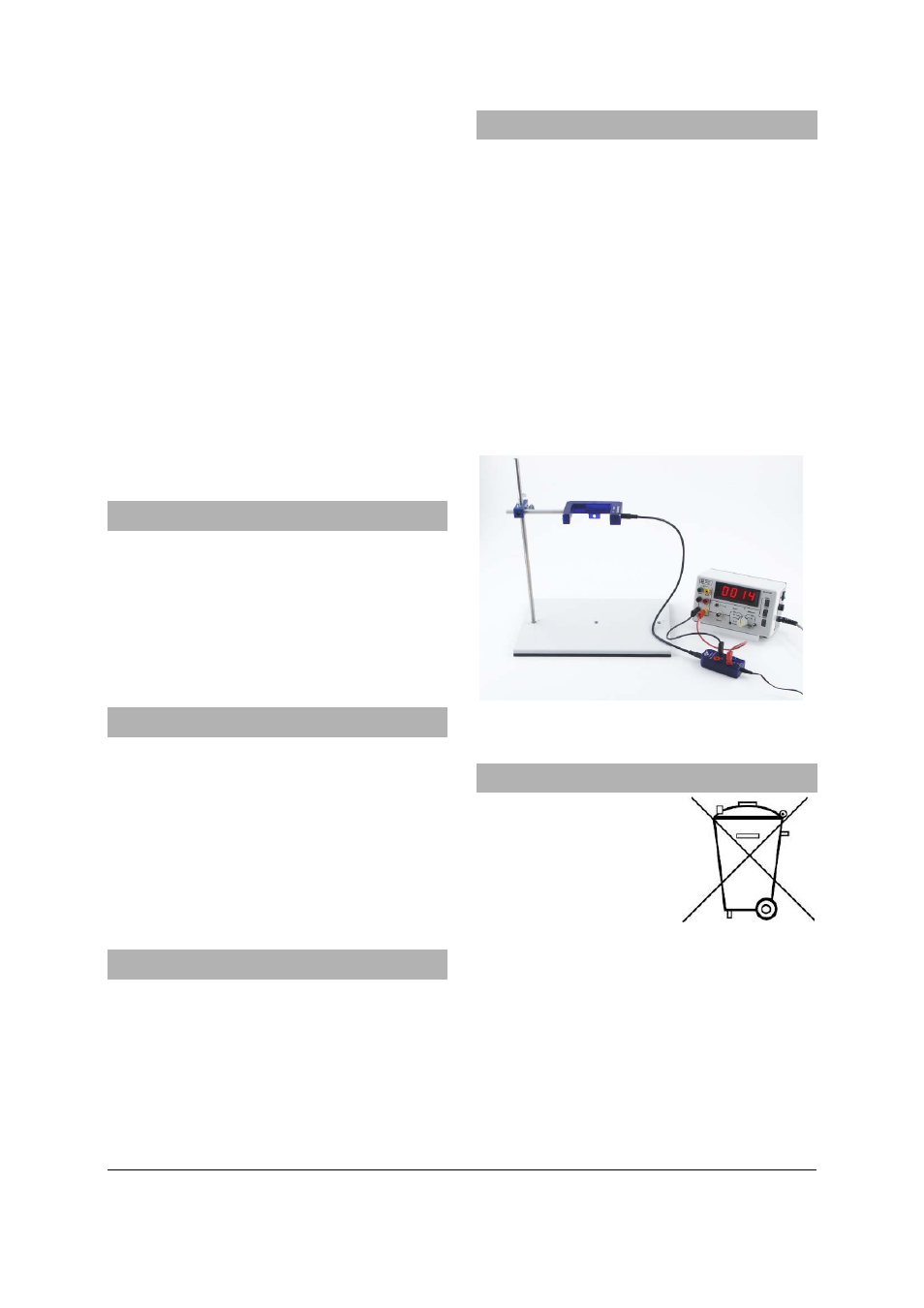
6. Sample experiment
Connecting a counter to the photo gate and
measuring the results
Required apparatus:
1 Photo gate
1000563
1 Connector box (@230 V)
1009955
or
1 Connector box (@115 V)
1009954
1 Counter
2 Safety experiment leads
Stand equipment
•
Connect the photo gate and counter to the
connector box as described in section 5.
•
Carry out the measurements you need.
Fig. 1 Experiment set-up with photo gate and counter
7. Disposal
Should the equipment need
to be scrapped, it must not
be disposed of in normal
household waste.
•
Packaging and compo-
nents should be dis-
posed of at local recy-
cling centres.