3B Scientific Sensor Holder for Stirling Engine G User Manual
Page 2
2
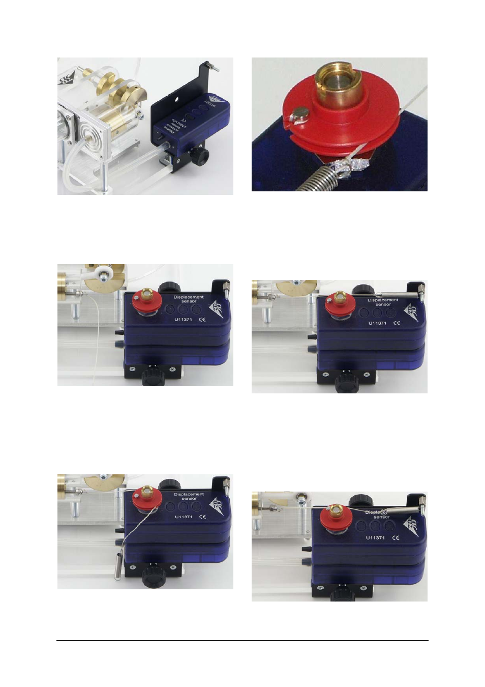
Fig. 2 Assembly of pressure sensor
•
Screw the cap nut attached to the string onto the
threaded rod of the working piston and fit the
displacement sensor in the top hole using a
knurled screw.
Fig. 3 Attachment of string to working piston and assem-
bly of displacement sensor
•
Move the working piston and the pulley to the
centre of their movement. Wrap the string
around the pulley and attach the spring to the
threaded rod. The string needs to go around the
small screw on the pulley.
Fig. 4 Positioning of working piston and pulley and how
to thread the string
Fig. 5 How the string is threaded around the pulley
•
Move the working piston out all the way, then
move the sensor holder in such a way that the
spring is at its minimum extension. The attach-
ments should be aligned such that the spring,
the string and the working piston all move in the
same plane.
Fig. 6
Alignment of sensor holder
•
Slowly turn the Stirling engine by hand and check
that none of the moving parts catch on the sensor
holder. Make sure, too, that the pulley does not
turn to its limit and that it is not touched by the
spring. If the spring does touch the pulley, it will
be extended too far when the working piston is at
the limit of its movement.
Fig. 7 Poorly aligned sensor holder whereby the string
sags at full extension