Set up the circuit as in fig. 5, Apply an anode voltage u, Of about 300 v – 3B Scientific Teltron Triode D, Vacuum User Manual
Page 3: Vary the anode voltage u
3
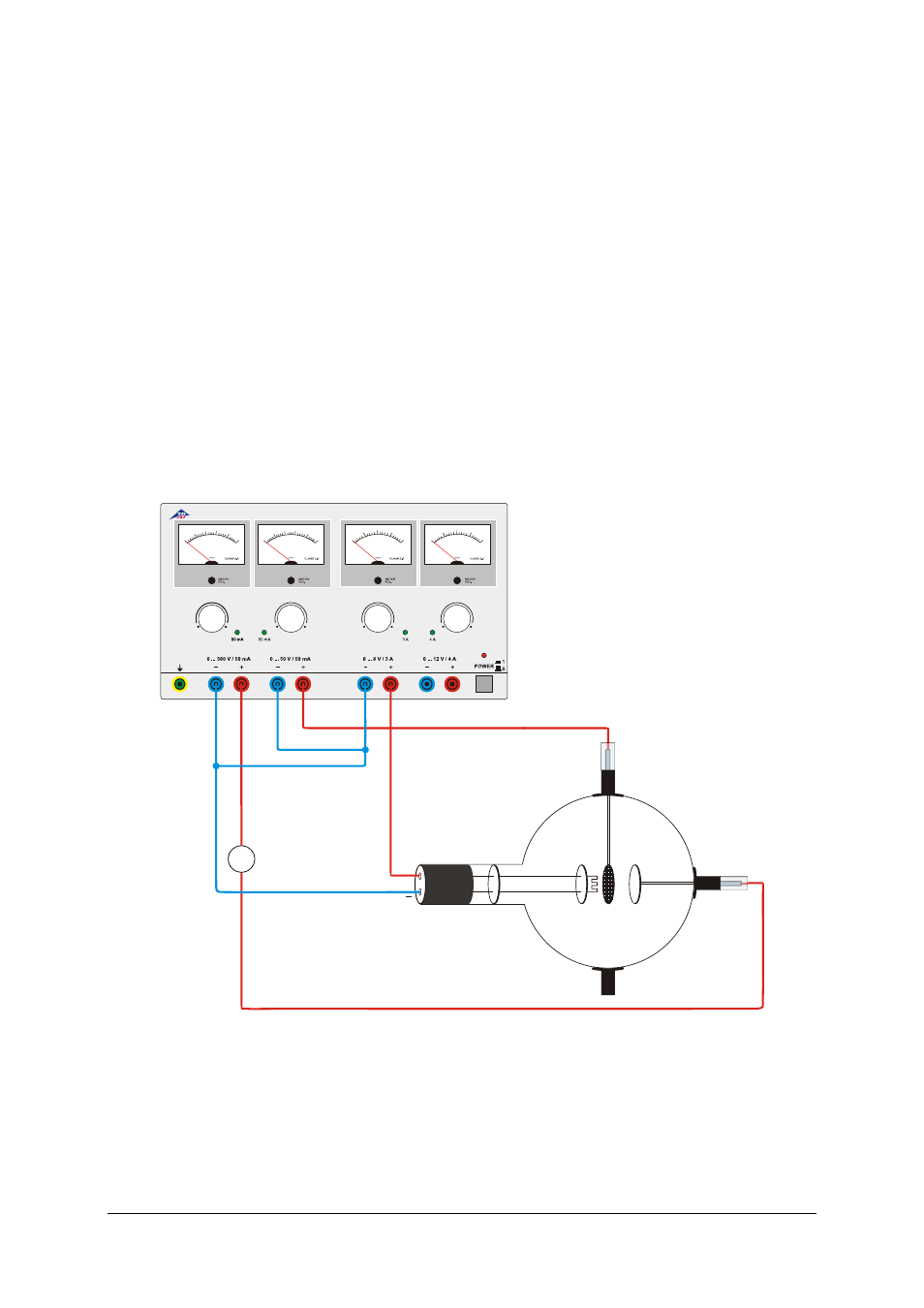
5.5 Generation of undamped LC oscillations
Also required:
1 Helmholtz pair of coils D
1000644
2 Barrel foot
1002834
1 Capacitor 250 pF or 1000 pF
1 Oscilloscope
Warning! When the anode voltage is
switched on, the metal parts of the coils are
live. Do not touch!
•
Only change circuits with power supply
equip-ment switched off.
•
Set up the circuit as in fig. 5.
•
Place the coils side by side as near one
another as possible.
•
Apply an anode voltage U
A
of about 300 V.
•
Observe the undamped oscillations on the
screen of the oscilloscope.
•
Rotate one of the coils to demonstrate that
that the occurance and amplitude of the os-
cillations depends on the relative position of
the two coils. Touch the coils only at the in-
sulated parts!
•
Vary the anode voltage U
A
between 100 and
500 V and observe that the amplitude of the
oscillations does not increase in direct pro-
portion to U
A
.
•
Carry out an experiment of the same kind
without capacitators so that the capacitance
of the oscillating circuit is formed only by the
self capacitance of the conductor.
DC POWER SUPPLY 0 ... 500 V
0 ... 500 V
0 ... 50 V
V
V
V
V
0
1
0
0 2
0
03
0
0 400
500
0 ... 12 V
0 ... 8 V
0
1
0
2
0 3
0 40
50
0
2
4
6
8
0
3
6
9
12
U
F
U
A
U
G
I
A
Fig. 1 Demonstration of anode current and determination of the polarity of the charge carriers