Technical data, Operation – 3B Scientific Geiger-Muller Counter Tube User Manual
Page 2
Elwe Didactic GmbH • Steinfelsstr. 6 • 08248 Klingenthal • Germany •
www.elwedidactic.com
3B Scientific GmbH • Rudorffweg 8 • 21031 Hamburg • Germany •
www.3bscientific.com
Subject to technical amendments
© Copyright 2007 3B Scientific GmbH
3. Technical data
Filling gas:
Neon-argon mixture,
with halogen as
quenching agent
Cathode dimensions:
39x14 mm²
Window:
Mica, 9 mm Ø
Surface density:
1.5 – 2.0 mg/cm²
Operating voltage:
400 – 600 V (recom-
mended voltage: 500
V)
Rel. gradient of plateau:
0.04%/V
Dead-time: 90
µs
Limiting resistance:
10 M
Ω, built into the
housing
Overall dimensions:
Approx. 85 mm x 25
mm Ø
Handling rod dimensions:
100 mm x 10 mm Ø
Mass:
Approx. 160 g
4. Operation
Note:
The protective cap does not allow
α-radiation to pass
through, and transmits
β-radiation only partially.
Remove the protective cap when appropriate before
starting measurement. Replace the cap after each
use, taking care not to touch the mica window.
For carrying out experiments the following additional
equipment is recommended:
HF cable, 1 m
U11255
Digital counter (230 V, 50/60 Hz)
U8533341-230
or
Digital counter (115 V, 50/60 Hz)
U8533341-115
Geiger-Müller box
U11391
•
Connect the Geiger-Müller counter tube to a
digital counter through an HF cable.
•
Set up the counter tube so that the radiation falls
squarely on the mica window.
•
If appropriate, remove the plastic protective cap.
•
Set the required measurement time on the
counter.
•
Switch the audible counting signal on or off as
required.
•
Start the measurement.
•
After the measurement, replace the protective
cap.
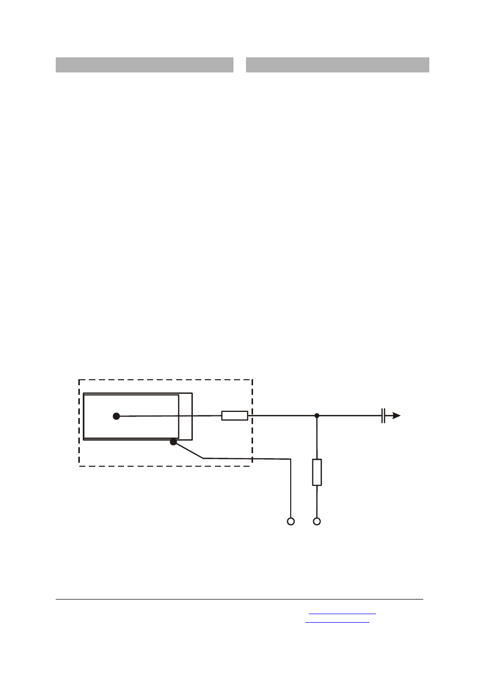
400 V... 600 V
10 M
Ω
220 pF
1 MΩ
Fig. 1. Schematic arrangement of the counter tube
.