3B Scientific Teltron Dual Beam Tube S User Manual
Page 3
3
y
y
x
DC
AC
AB
BC
R
2
2
2
2
2
+
=
=
=
=
2
2
2
2
2
⎥
⎥
⎦
⎤
⎢
⎢
⎣
⎡
+
=
y
y
x
R
y
2y
2 mm
D’ E’
A’
x
E
A
D
B
C
R
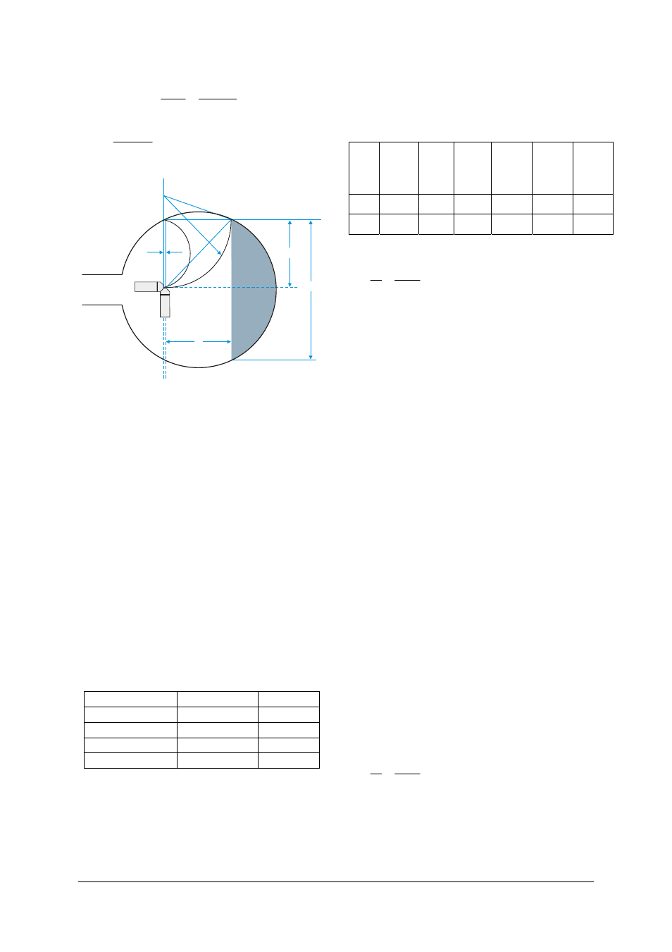
Fig. 1 Derivation of R
•
Connect up the tube as in Fig. 3.
•
Dim the room lighting.
•
Assure the correct positioning of the Helm-
holtz coils in Helmholtz configuration.
•
Set the heater voltage U
F
to 7 V and wait
about 1 minute for the heater temperature to
achieve thermal stability (see remarks in
section 7).
•
Set the anode voltage U
A
to 90 V (plate volt-
age U
P
= 0 V).
•
Set the current in the coils I
H
so that the
deviated beam passes through point A on
the edge of the fluorescent screen of the
tube. Simultaneously focus the beam using
a plate voltage U
P
of no more than 6 V.
•
Mark point A on the tube using a felt-tip pen.
•
Increase U
A
and set I
H
so that the deflected
beam always passes through A. Enter all the
values into a table.
U
A
in volts
I
H
in amps
I
H
2
90
100
110
120
•
Increase I
H
so that the deflected beam al-
ways passes through point E and enter the
values in a corresponding table.
•
Mark point E on the tube using a felt-tip pen.
•
Plot the graphs of the values from both ta-
bles
•
Use a vernier calliper to measure the diame-
ters AA’, EE’ and distance AE.
•
Complete the table and calculate R².
AE
mm
x =
AE+
2 mm
x
2
mm
2
2y =
EE’
mm
y =
EE’ /
2 mm
y
2
mm
2
R
2
mm
2
•
Replace the values in the equation
5
2
2
10
15
.
1
⋅
⋅
=
R
I
U
m
e
H
A
and calculate a mean value for e/m.
5.2 Deflection in a circular path and the de-
termination of e/m
•
Connect up the tube as in Fig. 4.
•
Assure the correct positioning of the Helm-
holtz coils in Helmholtz configuration.
•
Set the anode voltage U
A
to 100 V (plate
voltage U
P
= 0 V).
•
Set the current in the coils I
H
so that the
deflected beam moves in a circular path with
the plane AA’ tangential to it.
It is practical in this instance to observe the
beam from above, from where it appears as a
straight line and can be focused using U
P
to a
mximum of 6 V.
Note: the axial non-linearity of the beam has the
effect of pushing the beam out of the plane of
the electron gun. In order to obtain more accu-
rate results, the tube should be turned within the
brace that holds it so that the circular path is in
the plane of the gun. I
H
should also be modified
so that plane AA’ makes a good tangent with the
path. A slight angle to the axis of the tube is
tolerable. The beam travels in a slightly spiral-
ling path instead of an accurate circle.
•
Increase U
A
and set I
H
so that the plane AA’
always forms a tangent to the deflected
beam. Tabulate I
H
against U
A
and plot the
graph.
•
Evaluate R = AE/2 and R² = AE²/4 like in
experiment 5.1.
•
Replace the values in the equation
5
2
2
10
15
.
1
⋅
⋅
=
R
I
U
m
e
H
A
and calculate a mean value for e/m.