3B Scientific Optical Precision Bench D, 500 mm User Manual
Page 2
4
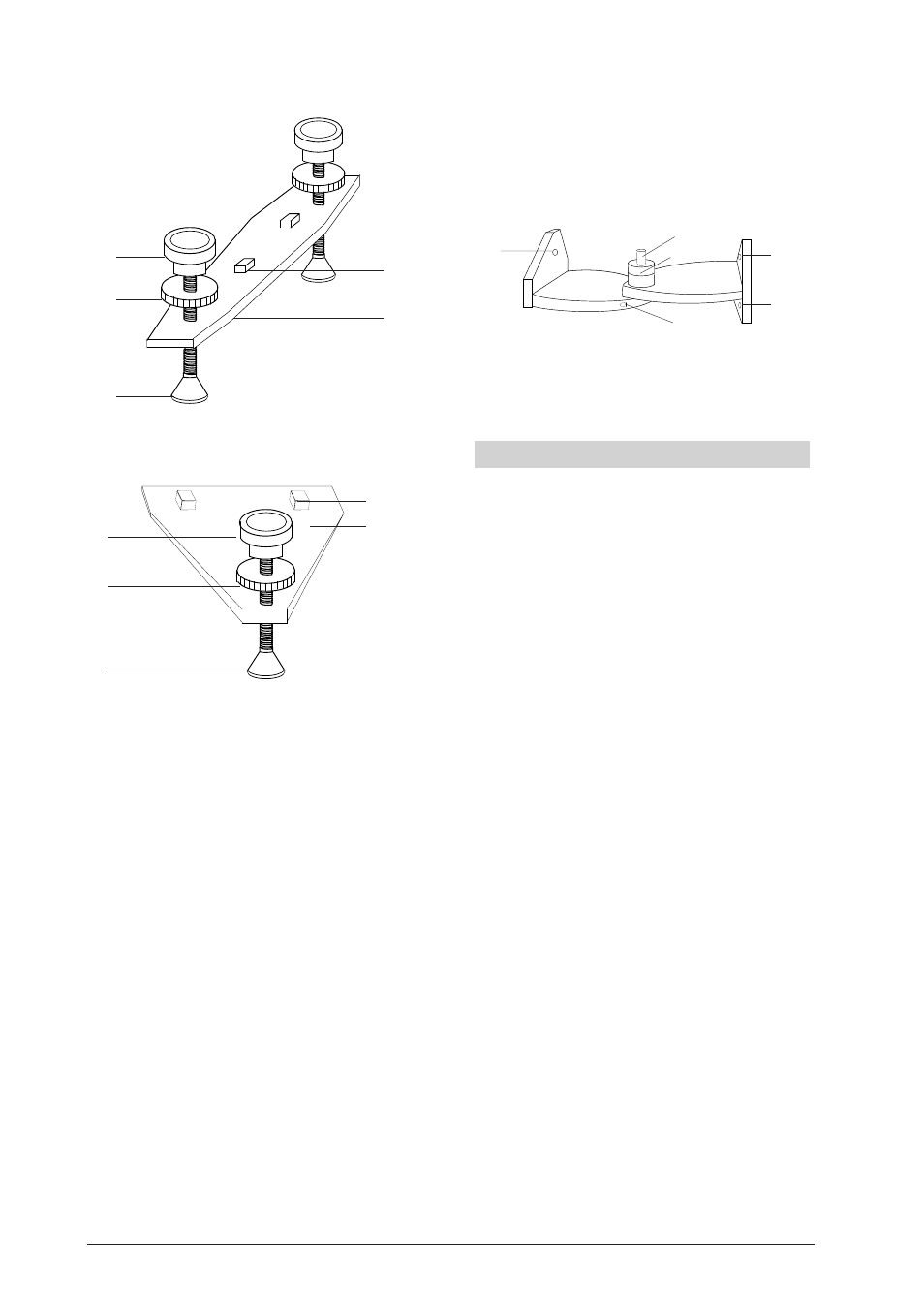
Fig. 2.1 Rail supports
Fig. 2.2 Single-point support
1
Adjustment screw to adjust the height
2
Grub-screw to secure the height
3
Stand base
4
Rail support
5
Square-socket screw to fasten the rail foot into the groove
1.3 Swivel joint
The swivel joint consists of black anodised aluminium
and can be swivelled around an angle of 90° in both
directions. A protractor has been included to set the
angle. In the rotational axis there is a sleeve to mount
optical components.
Rotational angle:
± 90°
Protractor:
±180°
Scale division:
1°
Sleeve height:
60 mm
Span width for shaft:
10 mm up to 14 mm
Figure 3
1
Drilled screw holes for fastening to the optical bench
2
Mount for protractor and sleeve
2. Operation
2.1 Assembly of the rail supports
•
Insert the square-socket screws into the guide
groove under the profile rail and fasten by tight-
ening them.
•
Adjust the height using the adjustment screw.
•
Use the grub-screw to secure the settings.
2.2 Assembly of the swivel joint
•
Take off the front plate by loosening the three fas-
tening screws.
•
Place the swivel joint on the rail and secure it by
tightening the three screws.
•
Connect the swivel joint to the second rail in like
fashion.
2.3 Recommended rider and assembly aids
•
For the assembly of elements in the optical axis:
Optical rider (U10310 to U10312 and U10315 to
U10317)
Double rider (U10340 to U10342)
•
To tilt element out of the optical axis:
Tilting rider (U10330)
•
To slide elements perpendicular to the optical
bench axis: sliding rider (U10320)
•
To position elements adjacent to the optical axis:
Extension arm (U10331)
2
4
5
1
3
1
2
3
4
5
1
2
1
1
1
2
3B Scientific GmbH • Rudorffweg 8 • 21031 Hamburg • Deutschland • www.3bscientific.com • Technical amendments are possible