Transceiver block diagram, Absolute maximum rating, Recommended operating environment – Approved Optics Approved ALLIED TELESIS AT-SP10LR User Manual
Page 5
Approved Optics, Inc.
www.ApprovedOptics.com
Page 5 of 9
AT-SP10LR-A
10GBASE-LR SFP+ SMF
1310NM 10KM REACH LC
Table 1: SFP+ Module PIN Definition
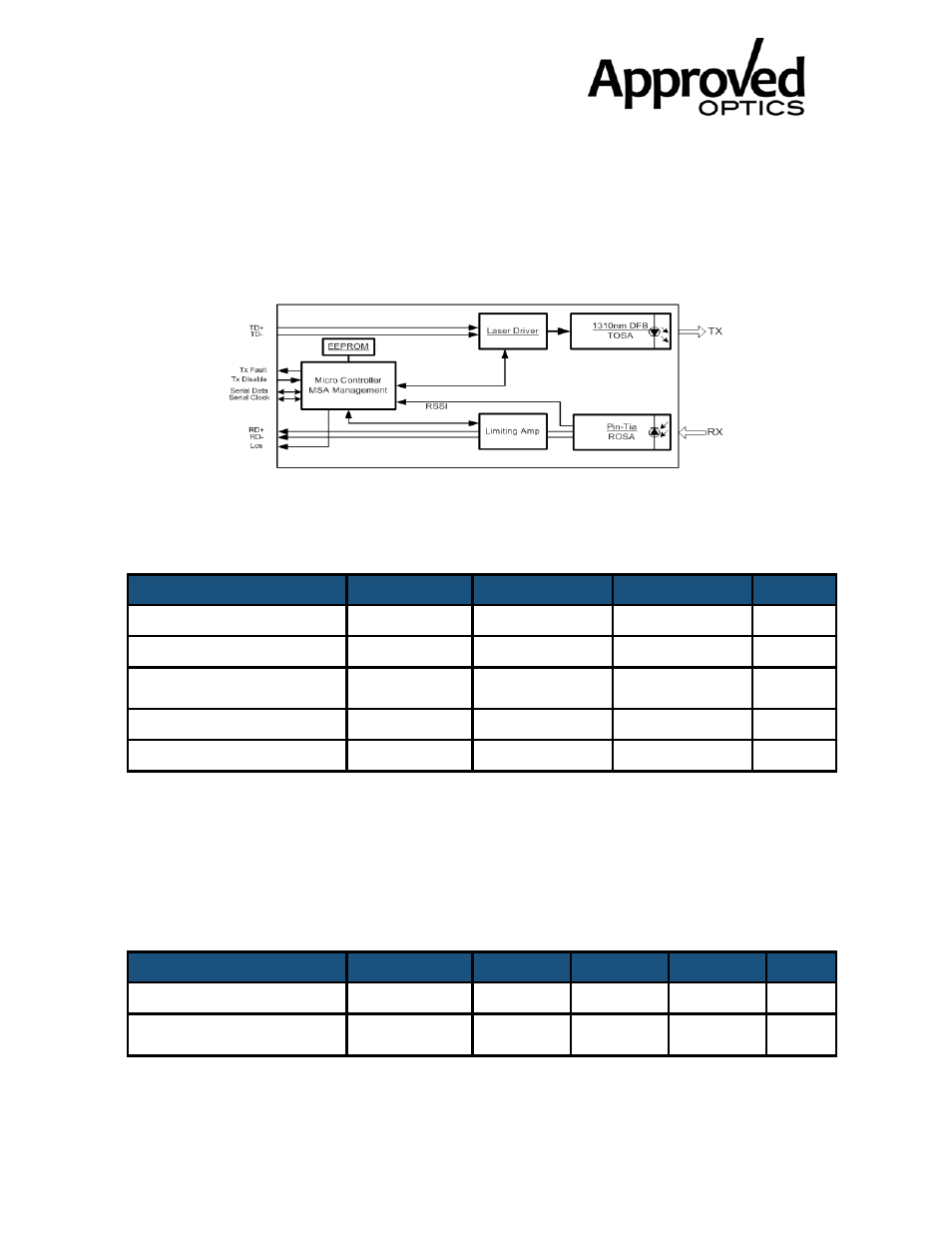
4. TRANSCEIVER BLOCK DIAGRAM
5. ABSOLUTE MAXIMUM RATING
These values represent the damage threshold of the module. Stress in excess of any of
Parameters
Symbol
Min.
Max.
Unit
Power Supply Voltage
Vcc
0
3.6
V
Storage Temperature
Tc
-40
85
°C
Operating Case
Temperature
Tc
0
70
°C
Relative Humidity
RH
5
95
%
RX Input Average Power
Pmax
-
0
dBm
the individual Absolute Maximum Ratings can cause immediate catastrophic damage to
the module even if all other parameters are within Recommended Operating
Table 2: Absolute Maximum Rating
6. RECOMMENDED OPERATING ENVIRONMENT
Recommended Operating Environment specifies parameters for which the
Parameters
Symbol
Min.
Typical
Max.
Unit
Power Supply Voltage
Vcc
3.135
3.3
3.465
V
Operating Case
Temperature
Tc
0
25
70
°C
electrical and optical characteristics hold unless otherwise noted.