0 functional description, Status register 2 – Rainbow Electronics LM83 User Manual
Page 14
1.0 Functional Description
(Continued)
Command Se-
lect Address
Power On Default State
Register Name
Register Function
<
P7:P0
>
hex
<
D7:D0
>
binary
<
D7:D0
>
deci-
mal
5Ch-6Fh and
F0h-FDh
Reserved for Future Use
FEh
0000 0001
1
RMID
Read Manufacturers ID
FFh
RSR
Read Stepping or Die
Revision Code
2.2 LOCAL and D1, D2 and D3 REMOTE TEMPERATURE REGISTERS (LT, D1RT, D2RT, and D3RT)
(Read Only Address 00h, 01h, 30h and 31h):
D7
D6
D5
D4
D3
D2
D1
D0
MSB
Bit 6
Bit 5
Bit 4
Bit 3
Bit 2
Bit 1
LSB
D7–D0: Temperature Data. One LSB = 1˚C. Two’s complement format.
2.3 STATUS REGISTERS 1 and 2
2.3.1 Status Register 1 (SR1) (Read Only Address 02h):
D7
D6
D5
D4
D3
D2
D1
D0
0
LHIGH
0
D2RHIGH
0
D2OPEN
D2CRIT
LCRIT
Power up default is with all bits “0” (zero).
D0: LCRIT: When set to a 1 indicates an Local Critical Temperature alarm.
D1: D2CRIT: When set to a 1 indicates a Remote Diode 2 Critical Temperature alarm.
D2: D2OPEN: When set to 1 indicates a Remote Diode 2 disconnect.
D4: D2RHIGH: When set to 1 indicates a Remote Diode 2 HIGH Temperature alarm.
D6: LHIGH: When set to 1 indicates a Local HIGH Temperature alarm.
D7, D5, and D3: These bits are always set to 0 and reserved for future use.
Status Register 2
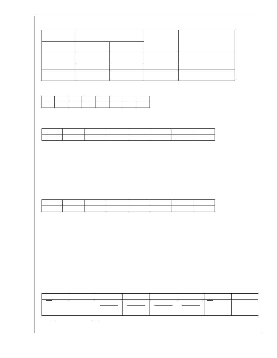
2.3.2 Status Register 2 (SR2) (Read Only Address 35h):
D7
D6
D5
D4
D3
D2
D1
D0
D1RHIGH
0
D1OPEN
D3RHIGH
0
D3OPEN
D3CRIT
D1CRIT
Power up default is with all bits “0” (zero).
D0: D1CRIT, when set to 1 indicates a Remote Diode 1 Critical Temperature alarm.
D1: D3CRIT, when set to 1 indicates a Remote Diode 3 Critical Temperature alarm.
D2: D3OPEN, when set to 1 indicates a Remote Diode 3 disconnect.
D4: D3RHIGH, when set to 1 indicates a Remote Diode 3 HIGH Temperature alarm.
D5: D1OPEN, when set to 1 indicates a Remote Diode 1 disconnect.
D7: D1RHIGH, when set to 1 indicates a Remote Diode 1
HIGH Temperature alarm.
D6, and D3: These bits are always set to 0 and reserved for future use.
2.4 MANUFACTURERS ID REGISTER
(Read Address FEh) Default value 01h.
2.5 CONFIGURATION REGISTER
(Read Address 03h/Write Address 09h):
D7
D6
D5
D4
D3
D2
D1
D0
INT mask
0
D1
T_CRIT_A
mask
D2
T_CRIT_A
mask
D3
T_CRIT_A
mask
Local
T_CRIT_A
mask
INT Inversion
0
Power up default is with all bits “0” (zero).
D7: INT mask: When set to 1 INT interrupts are masked.
LM83
www.national.com
14