2x4-channel, simultaneous-sampling 14-bit das – Rainbow Electronics MAX126 User Manual
Page 12
MAX125/MAX126
The circuit of Figure 10 shows a typical vector motor-
control application using all available inputs of the
MAX125/MAX126. CH1A and CH2A are connected
to two isolated Hall-effect current sensors and are a
part of the current (torque) feedback loop. The
MAX125/MAX126 digitize the currents and deliver raw
data to the following DSP and controller stages, where
the vector processing takes place. Sensorless vector
control uses a computer model for the motor and an
algorithm to split each output current into its magnetiz-
ing (stator current) and torque-producing (rotor current)
components.
If a 2- to 3-phase conversion is not practical, three cur-
rents can be sampled simultaneously with the addition
of a third sensor (not shown). Optional voltage
(position) feedback can be derived by measuring two
phase voltages (CH3A, CH4A). Typically, an isolated
differential amplifier is used between the motor and the
MAX125/MAX126. Again, the third phase voltage can
be derived from the magnitude (phase voltage) and its
relative phase.
For optimum speed control and good load regulation
close to zero speed, additional velocity and position
feedback are derived from an encoder or resolver and
2x4-Channel, Simultaneous-Sampling
14-Bit DAS
12
______________________________________________________________________________________
PRE
CLR
HC161
1/2 HC74
V
CC
V
CC
V
CC
ENP
ENT
LOAD
A
B
C
D
(LSB) 0
1
2
3
RCO
D
Q
Q
CLR
P0
P1
P2
P3
P4
P5
P6
P7
HC688
P = Q
Q0
Q1
Q2
V
CC
Q3
Q4
Q5
Q6
Q7
G
LATCH
CLOCK
(TO 16373 LATCH)
0
CH1
0
1
CH2
0
0
CH3
1
1
CH4
1
10k
EXTERNAL
CLOCK
EXTERNAL
CLOCK
RD
INT
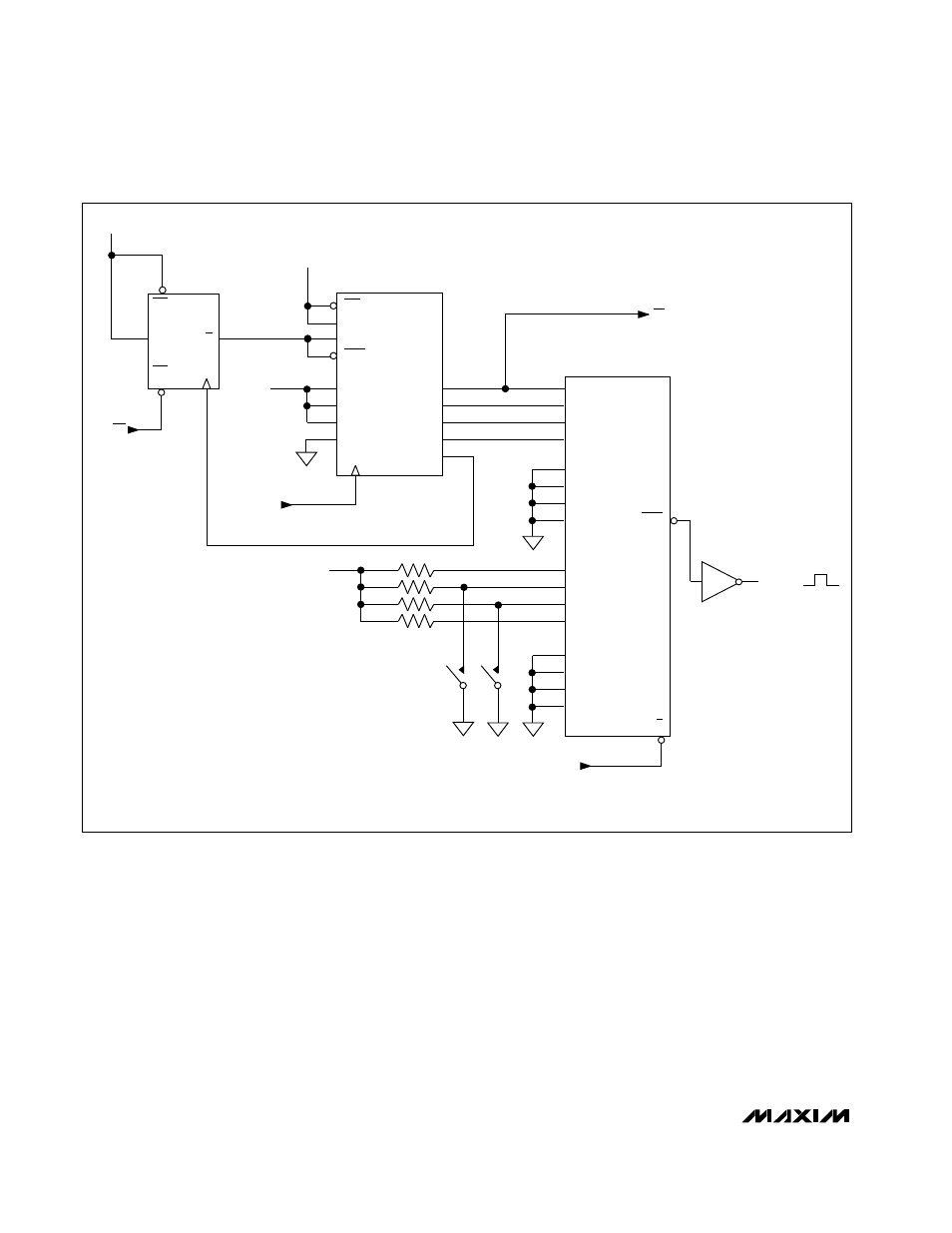
Figure 9. Output Demultiplexer Circuit