Rainbow Electronics MAX1714A User Manual
Page 3
Evaluates: MAX1714A
MAX1714A Evaluation Kit
_______________________________________________________________________________________
3
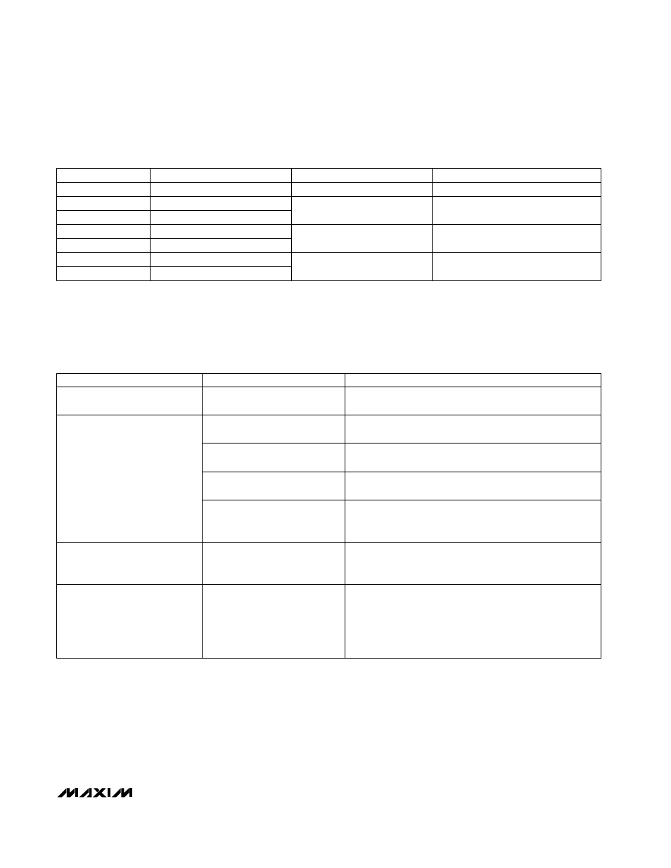
Table 4. Jumper JU4/JU5/JU6 Functions (Switching-Frequency Selection)
Table 5. Troubleshooting Guide
IMPORTANT: Don’t change the operating frequency without first recalculating component values because the frequency has a signifi-
cant effect on the preferred inductor value, peak current-limit level, MOSFET heating, PFM/PWM switchover point, output noise, efficien-
cy, and other critical parameters.
JUMPER
SHUNT LOCATION
FREQUENCY (kHz)
JU4, JU5, JU6
Off
300
JU4
On
TON PIN
Floating
JU5, JU6
Off
200
JU5
On
Connected to V
CC
JU4, JU6
Off
450
Connected to REF
JU6
On
JU4, JU5
Off
600
Connected to AGND
Circuit won’t start when SHDN
and +5V bias supply are cycled.
Output overvoltage due to
shorted high-side MOSFET
Replace the MOSFET.
Output overvoltage due to load
recovery overshoot
Reduce the inductor value, raise the switching frequency, or
add more output capacitance.
Overload condition
Remove the excessive load or raise the ILIM threshold by
changing R3/R9.
Broken connection, bad
MOSFET, or other
catastrophic problem
Troubleshoot the power stage. Are the DH and DL gate-
drive signals present? Is the 2V V
REF
present?
On-time pulses are erratic or
have unexpected changes in
period.
VBATT power source has poor
impedance characteristic
Add a bulk electrolytic bypass capacitor across the bench-
top power supply, or substitute a real battery.
Load-transient V
OUT
waveform
shows excess ringing.
OR
LX switching waveform exhibits
double-pulsing (pulses separat-
ed only by a 400ns min off-time).
Instability due to output
capacitors placed at the
feedback point
Add parasitic PC board trace resistance between the
feedback point and the output capacitor.
OR
Substitute a different capacitor type (OS-CONs, tantalums,
or aluminum electrolytics work well).
SYMPTOM
POSSIBLE PROBLEM
SOLUTION
Circuit won’t start when power is
applied.
Power-supply sequencing: +5V
bias supply was applied first
Cycle SHDN by removing and reinstalling JU1.