Typical operating characteristics (continued), Pin description – Rainbow Electronics MAX835 User Manual
Page 5
MAX834/MAX835
Micropower, Latching Voltage Monitors
in SOT23-5
_______________________________________________________________________________________
5
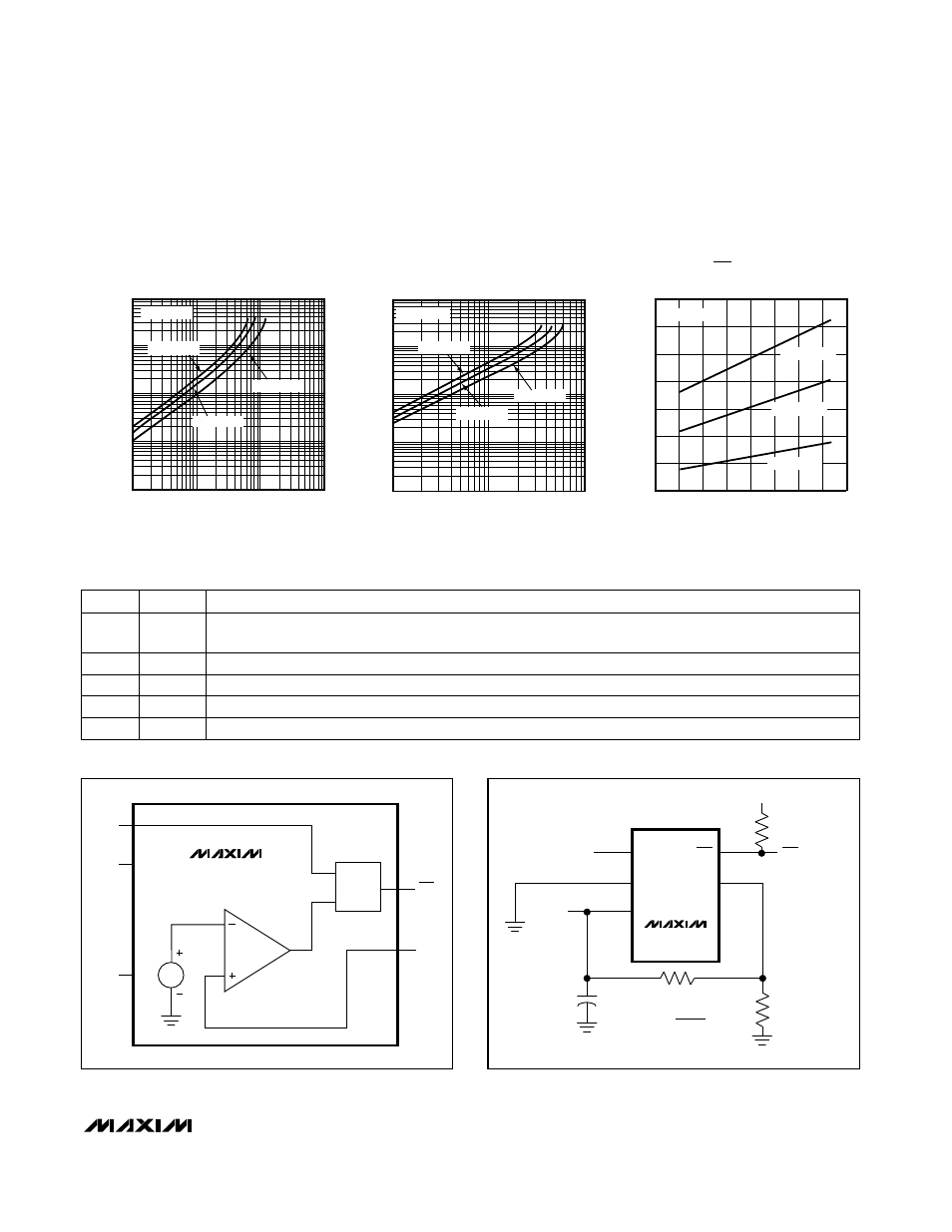
_____________________________Typical Operating Characteristics (continued)
(V
CC
= +5V, Typical Operating Circuit, T
A
= +25°C, unless otherwise noted.)
1
10
100
1k
10k
0.1
100
OUTPUT LOW VOLTAGE
vs. OUTPUT SINK CURRENT
OUTPUT SINK CURRENT (mA)
V
OL
(mV)
1
10
MAXMAX834/835-27
T
A
= +25°C
T
A
= +85°C
V
CC
= 3.6V
T
A
= -40°C
1
10
100
1k
10k
0.1
10
MAX835
OUTPUT HIGH VOLTAGE
vs. OUTPUT SOURCE CURRENT
OUTPUT SOURCE CURRENT (mA)
V
CC
- V
OH
(mV)
1
MAXMAX834/835-29
T
A
= +85°C
V
CC
= 3.6V
T
A
= -40°C
T
A
= +25°C
1.5
0.1
-60 -40
0
20
100
CLEAR TO OUT PROPAGATION DELAY
vs. TEMPERATURE
0.9
0.7
0.5
0.3
1.1
MAXMAX834/835-30
TEMPERATURE (°C)
PROPAGATION DELAY (
µ
s)
-20
40
60
80
1.3
V
CC
= 11.0V
V
CC
= 5.0V
V
CC
= 3.6V
V
IN
> V
TH
______________________________________________________________Pin Description
Open-Drain (MAX834) or Push/Pull (MAX835) Latched Output.
OUT is active low.
OUT
5
Noninverting Input to the Comparator. The inverting input connects to the internal 1.204V bandgap reference.
IN
4
System Supply Input
V
CC
3
PIN
System Ground
GND
2
Clear Input resets the latched output. With V
IN
> V
TH
, pulse CLEAR high for a minimum of 1µs to reset the
output latch. Connect to V
CC
to make the latch transparent.
CLEAR
1
FUNCTION
NAME
LATCH
OUT
V
CC
CLEAR
GND
1.204V
IN
MAX834
MAX835
Figure 1. Functional Diagram
Figure 2. Programming the Trip Voltage (V
TRIP
)
CLEAR
LATCH
OUT
V
CC
V
CC
V
CC
R2
R1
R
L
(MAX834 ONLY)
0.1
µ
F
OUT
CLEAR
GND
IN
MAX834
MAX835
V
TRIP
= (1.204)
(
)
(UNITS ARE OHMS
AND VOLTS)
R1 + R2
R2