Pin description – Rainbow Electronics MAX844 User Manual
Page 7
MAX840/MAX843/MAX844
Low-Noise, Regulated, -2V GaAsFET Bias
_______________________________________________________________________________________
7
______________________________________________________________Pin Description
Dual Mode is a trademark of Maxim Integrated Products.
MAX843
MAX844
1
2
3
—
4
8
7
6
5
MAX840
NAME
FUNCTION
1
C1+
Positive Terminal for C1
PIN
2
C1-
Negative Terminal for C1
3
NEGOUT
Negative Output Voltage (unregulated)
5
FB
Dual Mode™ Feedback Input. When FB is grounded, the output is preset to -2V. To
select other output voltages, connect FB to an external resistor divider (Figure 2b).
4
SHDN
Active-Low, TTL Logic-Level Shutdown Input
8
IN
Positive Power-Supply Input
7
GND
Ground
6
OUT
Regulated Negative Output Voltage
—
CONT
Control Voltage Input. To set V
OUT
, connect a resistor divider between OUT and a
positive control voltage between 0V and 10V (Figure 2c).
MAX840
-0.5V
REF
CHARGE
PUMP
IN
N
C1+
C1-
NEGOUT
SHDN
OUT
CONNECT TO
GND TO SET
V
OUT
= -2V
FB
GND
MAX843
MAX844
CHARGE
PUMP
IN
N
C1+
C1-
NEGOUT
SHDN
OUT
CONTROL
VOLTAGE
CONT
GND
R2
R1
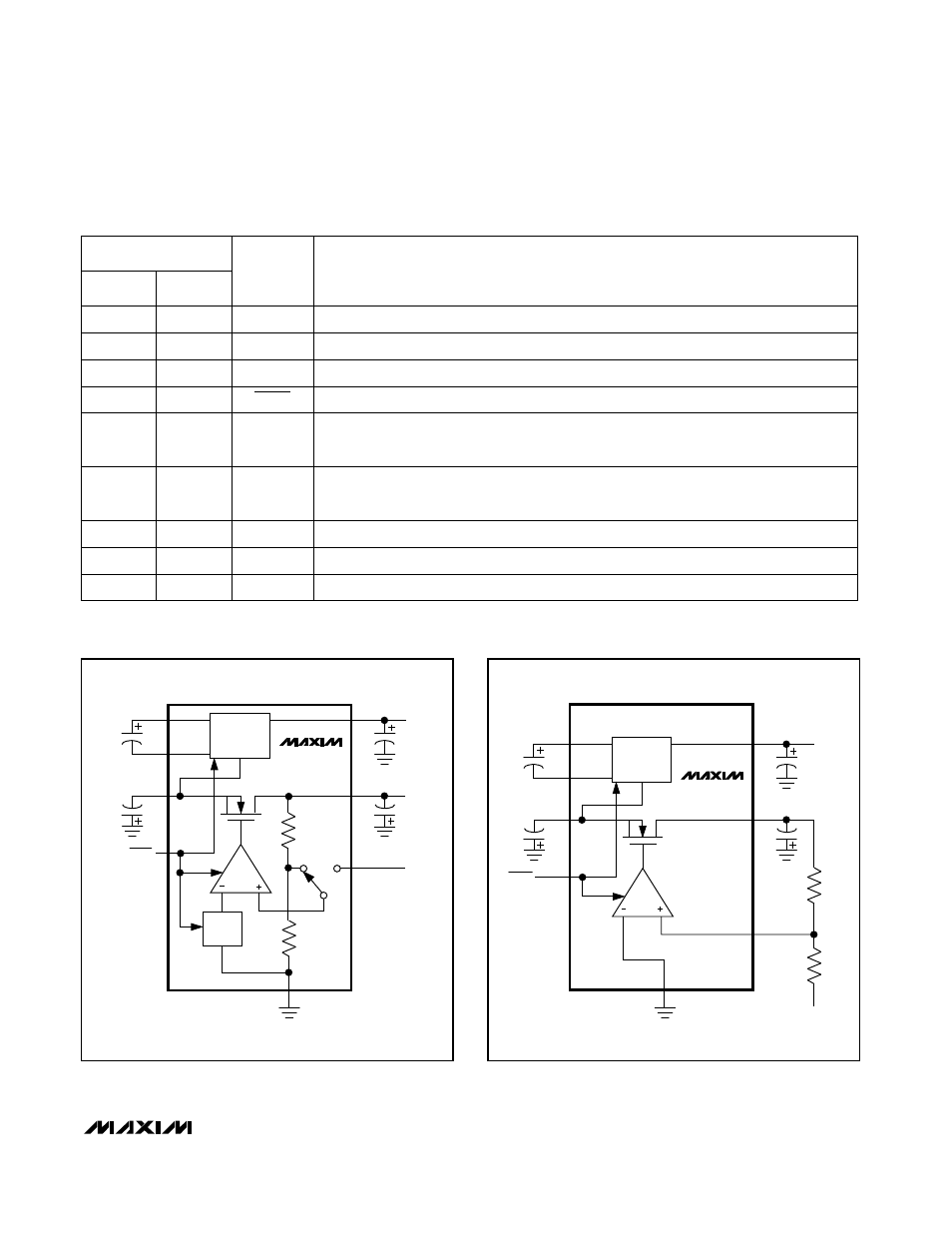
Figure 1a. MAX840 Block Diagram
Figure 1b. MAX843/MAX844 Block Diagram