Internal reference, Transfer function – Rainbow Electronics MAX1111 User Manual
Page 17
MAX1110/MAX1111
+2.7V, Low-Power, Multichannel,
Serial 8-Bit ADCs
______________________________________________________________________________________
17
Internal Reference
To use the MAX1110/MAX1111 with the internal refer-
ence, connect REFIN to REFOUT. The full-scale range
of the MAX1110/MAX1111 with the internal reference is
typically 2.048V with unipolar inputs, and ±1.024V with
bipolar inputs. The internal reference should be
bypassed to AGND with a 1µF capacitor placed as
close to the REFIN pin as possible.
Transfer Function
Table 4 shows the full-scale voltage ranges for unipolar
and bipolar modes. Figure 15 depicts the nominal, unipo-
lar I/O transfer function, and Figure 16 shows the bipolar
I/O transfer function when using a 2.048V reference.
Code transitions occur at integer LSB values. Output cod-
ing is binary, with 1LSB = 8mV (2.048V/256) for unipolar
operation and 1LSB = 8mV [(2.048V/2 - -2.048V/2)/256]
for bipolar operation.
POWERED UP
POWER-
DOWN
POWERED
UP
POWERED UP
DATA VALID
DATA VALID
DATA
INVALID
EXTERNAL
EXTERNAL
INTERNAL
S X X X X X 1 1
S
0 1
X
X
X
X
X
X X X X X
S
1 1
POWER-
DOWN
MODE
DOUT
DIN
CLOCK
MODE
SHDN
SETS EXTERNAL
CLOCK MODE
SETS EXTERNAL
CLOCK MODE
SETS POWER-
DOWN MODE
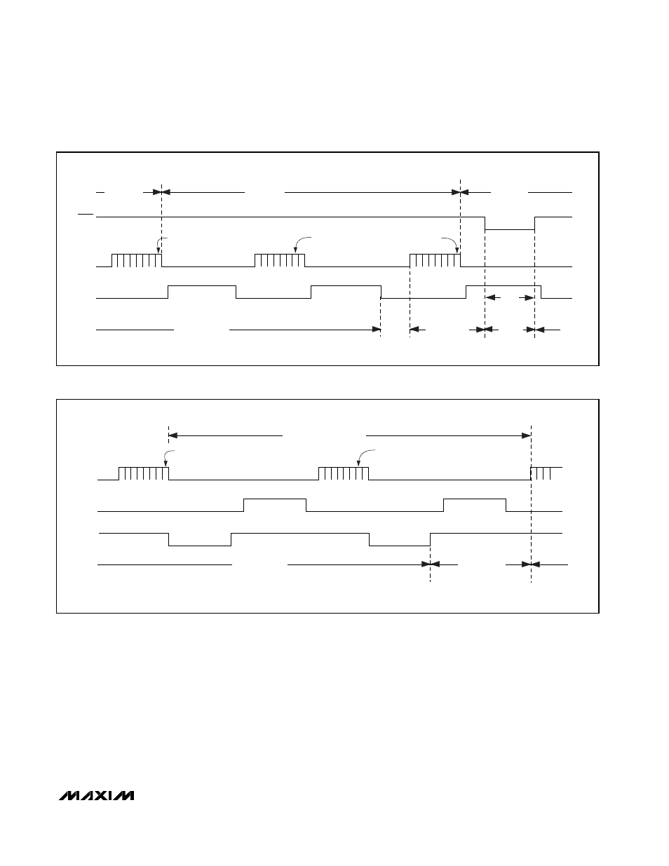
Figure 14a. Power-Down Modes, External Clock Timing Diagram
POWER-DOWN
POWERED
UP
POWERED UP
DATA VALID
DATA VALID
INTERNAL CLOCK MODE
S X X X X X 1 0
S
0 0
X
X
X
X
X
S
MODE
DOUT
DIN
SETS INTERNAL
CLOCK MODE
SETS POWER-DOWN MODE
CONVERSION
CONVERSION
SSTRB
Figure 14b. Power-Down Modes, Internal Clock Timing Diagram