Typical operating characteristics (continued), Pin description – Rainbow Electronics MAX1678 User Manual
Page 6
MAX1678
1-Cell to 2-Cell, Low-Noise,
High-Efficiency, Step-Up DC-DC Converter
6
_______________________________________________________________________________________
A
B
C
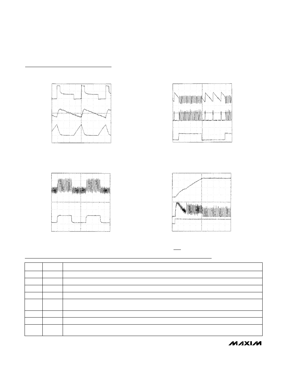
SWITCHING WAVEFORM
MAX1678-19
V
OUT
= 3.3V, V
BATT
= 1.2V, I
LOAD
= 10mA, C
OUT
= 10
µ
F,
L1 = SUMIDA CD43-470
A: LX, 2V/div B: V
OUT
, 50mV/div AC COUPLED
C: INDUCTOR CURRENT, 100mA/div
5
µ
s/div
Typical Operating Characteristics (continued)
(Circuit of Figure 7 (Fixed Mode, 3.3V) or Figure 8 (Adjustable Mode), T
A
= +25°C, unless otherwise noted.)
Pin Description
PIN
Battery-Power Input
BATT
1
FUNCTION
NAME
A
B
C
LOAD-TRANSIENT RESPONSE
MAX1678-20
V
OUT
= 3.3V, V
BATT
= 1.2V, C
OUT
= 10
µ
F,
L1 = SUMIDA CD43-470,
A: V
OUT
, 50mV/div, AC COUPLED B: INDUCTOR CURRENT,
C: LOAD, 2mA to 12mA 100mA/div
100
µ
s/div
A
B
LINE-TRANSIENT RESPONSE
MAX1678-21
V
OUT
= 3.3V, V
BATT
= 1.2V, I
LOAD
= 10mA, C
OUT
= 10
µ
F,
L1 = SUMIDA CD43-470
A: V
OUT
, 50mV/div, AC COUPLED B: V
IN
, 1V/div, 1.2V to 2.2V
200
µ
s/div
A
B
C
POWER-UP RESPONSE
MAX1678-22
V
OUT
= 3.3V, V
BATT
= 1.2V, I
LOAD
= 10mA, C
OUT
= 10
µ
F,
L1 = SUMIDA CD43-470
A: V
OUT
, 1V/div B: INDUCTOR CURRENT, 100mA/div
C: SHDN, 5V/div
100
µ
s/div
Power-Fail Input. When the voltage at PFI is below 614mV, PFO sinks current.
PFI
2
Active-Low Shutdown. Connect SHDN to BATT for normal operation.
SHDN
4
Open-Drain Power-Fail Output. PFO sinks current when PFI is below 614mV.
PFO
3
Ground
GND
6
Power Output and IC Power Input (bootstrapped). OUT is the feedback input for 3.3V operation. Connect
the filter capacitor close to OUT.
OUT
8
N-Channel MOSFET Switch Drain and P-Channel Synchronous-Rectifier Drain
LX
7
Dual-Mode Feedback Input. Connect FB to GND for fixed-output operation (3.3V). Connect FB to a feed-
back-resistor network for adjustable output voltage operation (2V to 5.5V). FB regulates to 1.23V.
FB
5