Table 1. component suppliers – Rainbow Electronics MAX723 User Manual
Page 6
MAX756/MAX757
3.3V/5V/Adjustable-Output,
Step-Up DC-DC Converters
6
_______________________________________________________________________________________
where V
IN
is the desired threshold of the low-battery
detector, R3 and R4 are the input divider resistors at
LBI, and V
REF
is the internal 1.25V reference.
Since the LBI current is less than 100nA, large resistor
values (typically 10k
Ω
to 200k
Ω
) can be used for R3
and R4 to minimize loading of the input supply.
When the voltage at LBI is below the internal threshold,
LBO sinks current to GND. A pull-up resistor of 10k
Ω
or more connected from LBO to V
OUT
can be used
when driving CMOS circuits. Any pull-up resistor con-
nected to LBO should not be returned to a voltage
source greater than V
OUT
. When LBI is above the
threshold, the LBO output is off. The low-battery com-
parator and reference voltage remain active when the
MAX756/MAX757 is in shutdown mode.
If the low-battery comparator is not used, connect LBI
to V
IN
and leave LBO open.
Inductor Selection
The inductors should have a saturation (incremental)
current rating equal to or greater than the peak switch-
current limit, which is 1.2A worst-case. However, it’s
generally acceptable to bias the inductor into satura-
tion by 20%, although this will reduce the efficiency.
The 22µH inductor shown in the typical applications cir-
cuit is sufficient for most MAX756/MAX757 application
circuits. Higher input voltages increase the energy
transferred with each cycle, due to the reduced
input/output differential. Minimize excess ripple due to
increased energy transfer by reducing the inductor
value (10µH suggested).
The inductor’s DC resistance significantly affects effi-
ciency. For highest efficiency, limit L1’s DC resistance
to 0.03
Ω
or less. See Table 1 for a list of suggested
inductor suppliers.
Table 1. Component Suppliers
AVX
USA:
(207) 282-5111, FAX (207) 283-1941
(800) 282-9975
CoilCraft
USA:
(708) 639-6400, FAX (708) 639-1969
Coiltronics
USA:
(407) 241-7876, FAX (407) 241-9339
Collmer
Semiconductor
USA:
(214) 233-1589
Motorola
USA:
(602) 244-3576, FAX (602) 244-4015
Nichicon
USA:
(708) 843-7500, FAX (708) 843-2798
Japan: +81-7-5231-8461, FAX (+81-) 7-5256-4158
Nihon
USA:
(805) 867-2555, FAX (805) 867-2556
Japan: +81-3-3494-7411, FAX (+81-) 3-3494-7414
Sanyo OS-CON
USA:
(619) 661-6835
Japan: +81-720-70-1005, FAX (+81-720-) 70-1174
Sprague
USA:
(603) 224-1961, FAX (603) 224-1430
Sumida
USA:
(708) 956-0666
Japan: +81-3-3607-5111, FAX (+81-3-) 3607-5428
United
Chemi-Con
USA:
(708) 696-2000, FAX (708) 640-6311
Capacitor Selection
A 100µF, 10V surface-mount (SMT) tantalum capacitor
typically provides 50mV output ripple when stepping
up from 2V to 5V at 200mA. Smaller capacitors, down
to 10µF, are acceptable for light loads or in applica-
tions that can tolerate higher output ripple.
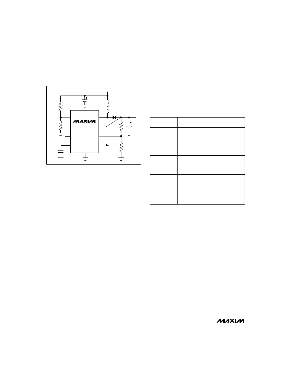
MAX757
REF
3
LX
7
C1
150
µ
F
GND
OUT
6
V
IN
D1
1N5817
V
OUT
LBO
4
8
C3
0.1
µ
F
L1
22
µ
H
LBI
5
C2
100
µ
F
SHDN
1
FB
2
R1
R2
R3
R4
Figure 1. Standard Application Circuit
PRODUCTION
METHOD
INDUCTORS
CAPACITORS
Surface-Mount
AVX
TPS series
Sprague
595D series
Miniature
Through-Hole
Sumida
RCH654-220
Low-Cost
Through-Hole
Sumida
CD54-220 (22µH)
CoilCraft
DT3316-223
Coiltronics
CTX20-1
Sanyo OS-CON
OS-CON series
low-ESR organic
semiconductor
CoilCraft
PCH-27-223
Nichicon
PL series
low-ESR
electrolyic
United Chemi-Con
LXF series