Ordering information, Connection diagram, Pin description – Rainbow Electronics LM27 User Manual
Page 2
Ordering Information
For more detailed information on the suffix meaning see the part number template at the end of the Electrical Characteris-
tics Section. Contact National Semiconductor for other set points and output options.
Order Number
Top Mark
NS Package
Number
Trip Point Setting
Output Function
Bulk Rail
3000 Units in Tape & Reel
LM27CIM5-1HJ
LM27CIM5X-1HJ
T1HJ
MA05B
130˚C
Open Drain OS
LM27CIM5-2HJ
LM27CIM5X-2HJ
T2HJ
MA05B
140˚C
Open Drain OS
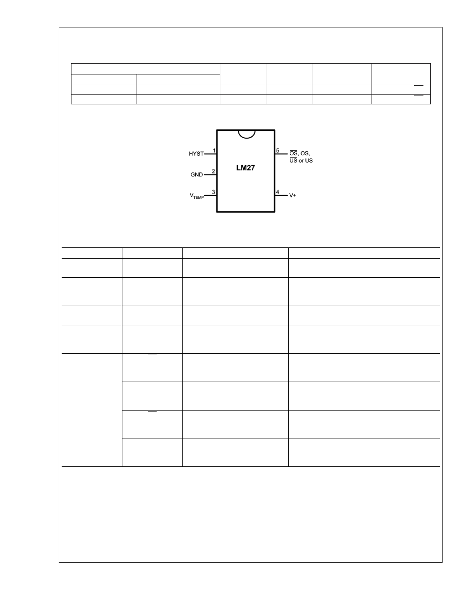
Connection Diagram
20030702
Pin Description
Pin Number
Pin Name
Function
Connection
1
HYST
Hysteresis control, digital
input
GND for 10˚C or V
+
for 2˚C
2
GND
Ground, connected to the
back side of the die through
lead frame.
System GND
3
V
TEMP
Analog output voltage
proportional to temperature
Leave floating or connect to a high impedance
node.
4
V
+
Supply input
2.7V to 5.5V with a 0.1µF bypass capacitor.
For PSRR information see Section Titled
NOISE CONSIDERATIONS.
5
OS
Overtemperature Shutdown
open-drain active low
thermostat digital output
Controller interrupt, system or power supply
shutdown; pull-up resistor
≥ 10kΩ
OS
Overtemperature Shutdown
totem-pull active high
thermostat digital output
Controller interrupt, system or power supply
shutdown
US
Undertemperature Shutdown
open-drain active low
thermostat digital output
System or power supply shutdown; pull-up
resistor
≥ 10kΩ
US
Undertemperature Shutdown
totem-pull active high
thermostat digital output
System or power supply shutdown
Note: pin 5 functionality and trip point setting are programmed during LM27 manufacture.
LM27
www.national.com
2