Rainbow Electronics MAX1760 User Manual
Page 6
MAX1760
0.8A, Low-Noise, 1MHz,
Step-Up DC-DC Converter
6
_______________________________________________________________________________________
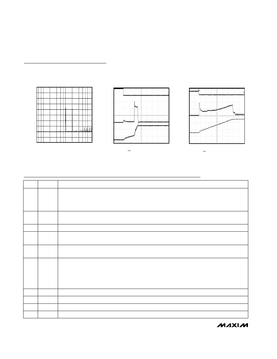
NOISE SPECTRUM
MAX1760-13
10
1
0.1
16
4
0
12
8
FREQUENCY (MHz)
NOISE (mV
RMS
)
TURN-ON WAVEFORMS
NO SOFT-START COMPONENTS
MAX1760-14
OV
C
A
B
t = 2ms/div
A = ON, 5V/div
B = INPUT CURRENT, 500mA/div
C = V
OUT
, 2V/div
SOFT-START WAVEFORMS
R
SS
= 500k
Ω, C
SS
= 0.1
µF
MAX1760-15
0V
C
A
B
2.00ms/div
A = ON, 5V/div
B = INPUT CURRENT, 100mA/div
C = V
OUT
, 2V/div
Pin Description
Typical Operating Characteristics (continued)
(Circuit of Figure 2, V
IN
= 2.4V, V
OUT
= 3.3V, T
A
= +25°C, unless otherwise noted.)
Power Output. P-channel synchronous-rectifier source.
POUT
9
Shutdown Control Input. When ON = high, the IC is in shutdown. Connect ON to GND for normal operation.
ON
10
IC Power, Supplied from the Output. Bypass to GND with a 0.68µF ceramic capacitor, and connect to POUT
with a series 4.7
Ω resistor (Figure 2).
OUT
5
Clock Input for the DC-DC Converter. Also serves to program operating mode of switcher as follows:
CLK/SEL = LO: Normal operation—operates at a fixed frequency, automatically switching to low-power
mode if load is minimized.
CLK/SEL = HI: Forced PWM mode—operates in low-noise, constant-frequency mode at all loads.
CLK/SEL = Clocked: Forced PWM mode with the internal oscillator synchronized to CLK in 500kHz to
1200kHz range.
CLK/SEL
6
Source of N-Channel Power MOSFET Switch
PGND
7
Inductor Connection
LX
8
DC-DC Converter Feedback Input. To set fixed output voltage of +3.3V, connect FB to ground. For
adjustable output of 2.5V to 5.5V, connect to a resistive divider from OUT to GND. FB set point = 1.24V.
FB
4
Ground. Connect to PGND with short trace.
GND
3
PIN
1.250V Voltage Reference Bypass. Connect a 0.22µF ceramic bypass capacitor to GND. Up to 50µA of
external load current is allowed.
REF
2
N-Channel Current-Limit Control. For maximum current limit, connect to REF. To reduce current, supply a
voltage between REF and GND by means of a resistive voltage-divider. If soft-start is desired, connect a
capacitor from ISET to GND. When ON = high, or V
REF
<80% of nominal value, an on-chip 100k
Ω switched
resistor discharges this pin to GND.
ISET
1
FUNCTION
NAME