Rainbow Electronics MAX1625 User Manual
Page 13
MAX1624/MAX1625
High-Speed Step-Down Controllers with
Synchronous Rectification for CPU Power
______________________________________________________________________________________
13
across the current-sense resistor (R1). When the induc-
tor current ramps up to the current-sense threshold, the
MOSFET turns off and interrupts the flow of current from
the supply. This causes the magnetic field in the induc-
tor to collapse, resulting in a voltage surge that forces
the rectifier diode (D1) or MOSFET body diode (N2) on
and keeps the inductor current flowing in the same
amplitude and direction. At this point, the synchronous
rectifier MOSFET turns on until the end of the cycle to
reduce conduction losses across the rectifier diode.
The current through the inductor ramps back down,
transferring the stored energy to the output filter capac-
itor and load. The output filter capacitor stores energy
when inductor current is high and releases it when
inductor current is low, smoothing the voltage delivered
to the load.
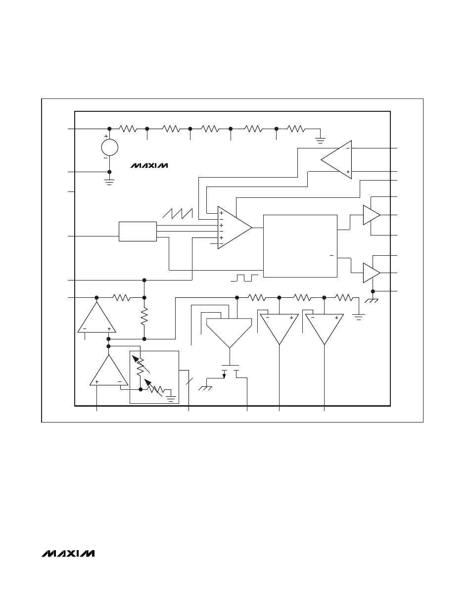
The MAX1624/MAX1625 use a current-mode pulse-
width-modulation (PWM) control scheme (Figures 3
and 4). The output voltage is regulated by switching at
a constant frequency and then modulating the peak
inductor current to change the energy transferred per
pulse and to adjust to changes in the load. The output
+
-
+
-
REF
REF4
AGND
REF3
REF2
REF
FB
D0–D4
PWROK
PDRV
NDRV
CC2
CC1
REF1
5
N
10k
40k
WINDOW
CONTROL AND
DRIVE LOGIC
OSCILLATOR
SLOPE
COMPENSATION
REF
AGND
V
CC
FREQ
REF
REF1
REF2
REF3
REF4
CSL
CSH
LG
BST
DH
LX
V
DD
DL
RESET
Q
Q
SET
PGND
MAX1624
Figure 3. MAX1624 Simplified Block Diagram